Limiting an X-ray beam in connection with dental imaging

a technology a connection, which is applied in the field of limiting an x-ray beam in connection, can solve the problems of increasing the construction cost, unable to adjust the aperture position, and imposing restrictions on the space available in the imaging apparatus

Active Publication Date: 2012-03-06
PLANMECA
View PDF18 Cites 11 Cited by
  • Summary
  • Abstract
  • Description
  • Claims
  • Application Information

AI Technical Summary

Benefits of technology

[0009]The current invention provides the advantage of making it possible to adjust the shape of the aperture limiting an x-ray beam of an extra oral imaging apparatus in two dimensions at a reasonable cost by using a single collimator construction and one actuator only. By the combined use of only one actuator, to operate the overlapping plate construction of the invention, the space the construction occupies in the imaging apparatus may be arranged to be reasonable yet x-ray beams of different shapes in two dimensions may be formed without having to arrange the plate elements replaceable. Reasonable number of components only is needed to realize the construction.

Problems solved by technology

However, the space available in imaging apparatus often imposes certain restrictions as to the number of different apertures that can be arranged in a single plate as well as to the number of plates as such that can be arranged into the apparatus.
In case the plates are arranged releasably connected and changeable, the arrangements needed allowing the replacement also involve certain problems regarding convenience of use of the apparatus.
However, the use of several actuators leads to increased cost of the construction, to complex electronics for controlling the actuators and to a certain space requirement for the actuators.
Further, regarding the construction of DE 32 36 082, it enables a synchronized movement of the plates limiting the beam only and also offers no means to adjust the location of the aperture to be formed, only its width.
Yet another aspect is that when a beam is limited by two plate elements arranged next to each other, should the aperture be adjustable e.g. in two perpendicular directions, two such pairs of plate elements would be needed which, obviously, would lead to an even greater space requirement.

Method used


Image

  • Limiting an X-ray beam in connection with dental imaging
  • Limiting an X-ray beam in connection with dental imaging
  • Limiting an X-ray beam in connection with dental imaging

Examples


Embodiment Construction

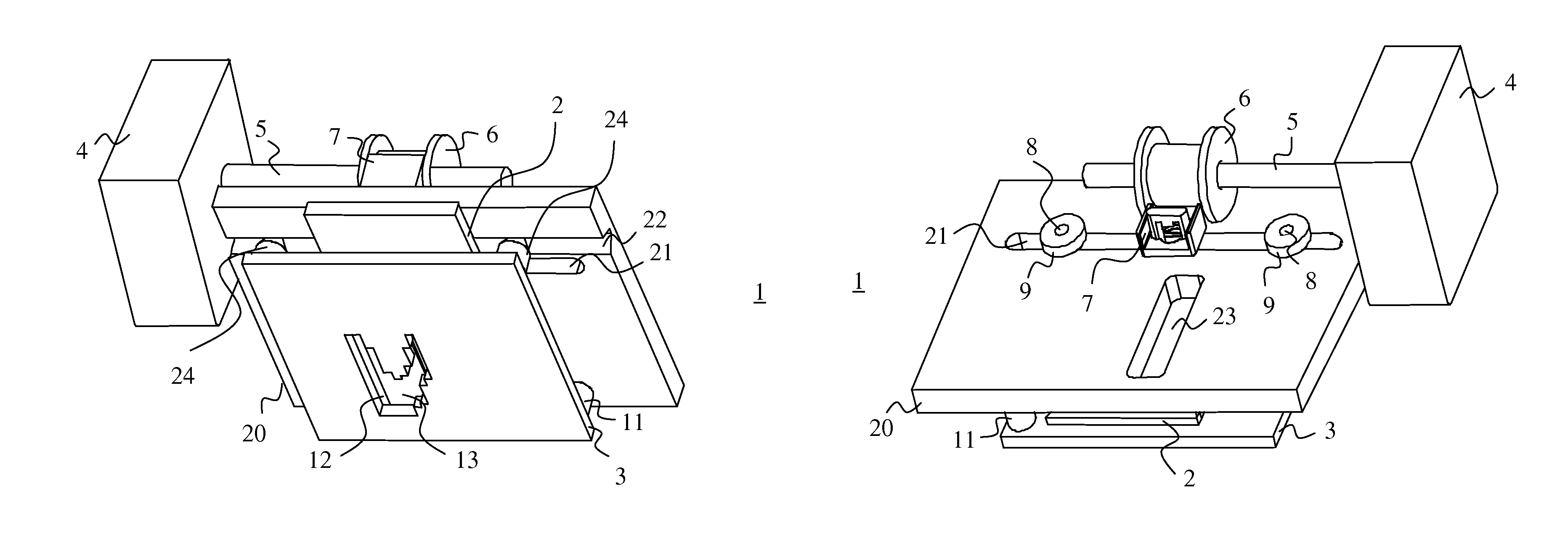
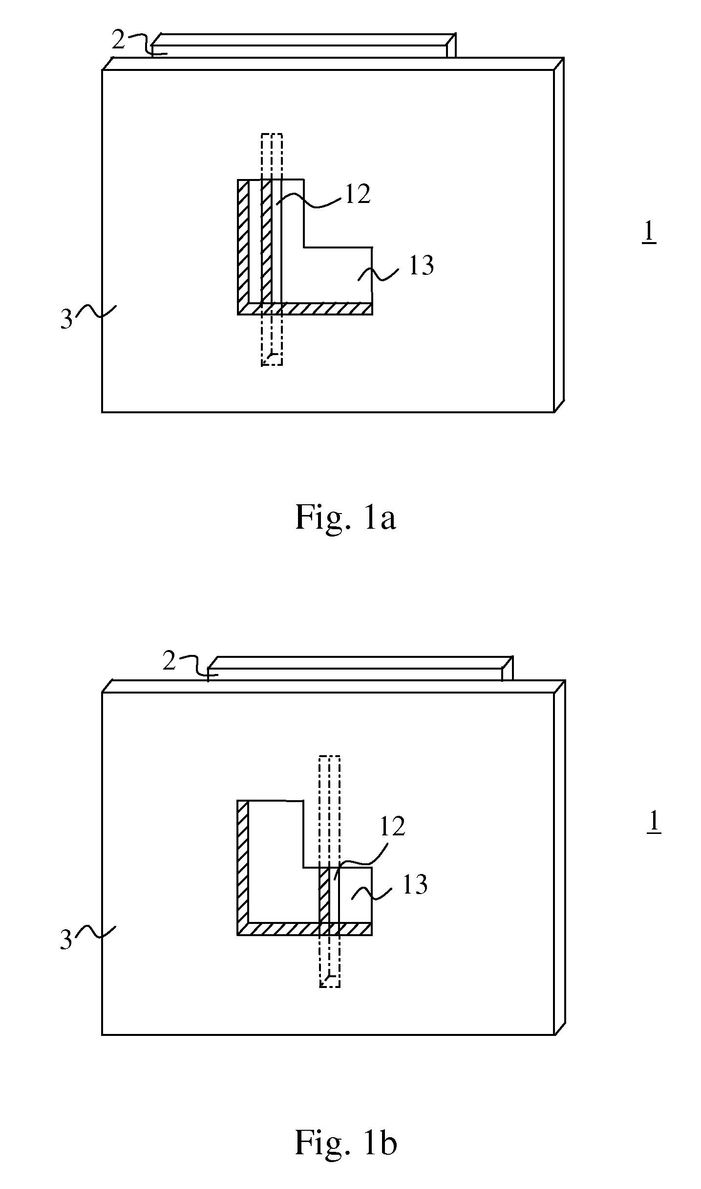
[0016]FIGS. 1a and 1b present a front view of plate elements of one embodiment of the invention. These figures show the plates only, a drive mechanism of the plate mechanism according to the invention will be discussed further below.

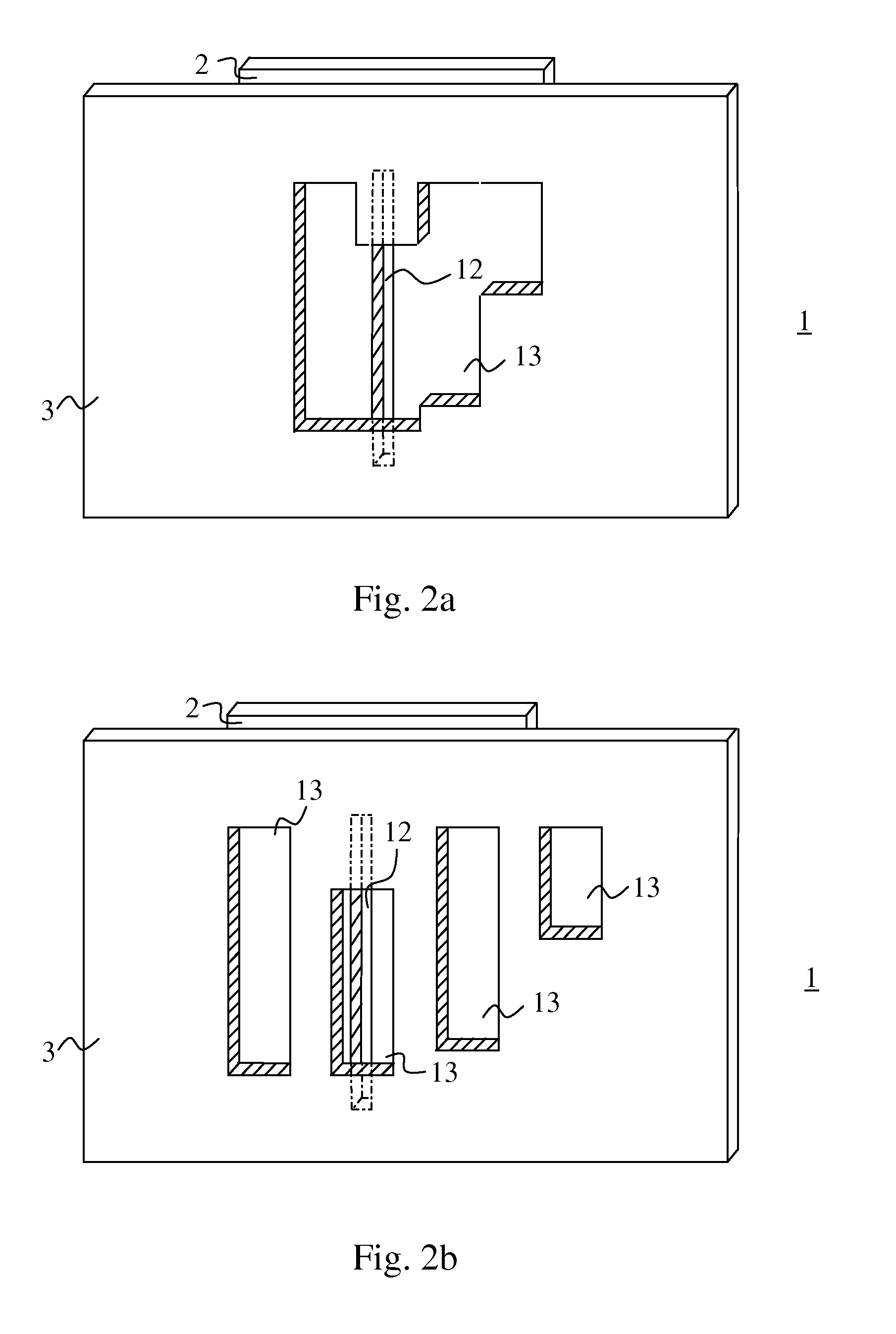
[0017]The plate mechanism (1) according to FIG. 1 comprises a first plate element (2) and a second plate element (3). The first plate element (2) includes a first slot (12) and the second plate element (3) includes a second slot (13). The first slot (12) of the first plate element (2) is arranged to be rectangular and its horizontal dimension to be substantially smaller than its vertical dimension. The second slot (13) is arranged to have two portions of different heights. The construction is designed to make possible arranging the slots (12, 13) of the first and second plate elements (2, 3) to lie on top of each other, by arranging at least portions of the plate elements (2, 3) movable on different planes. The first slot (12) is arranged to be at least ...


PUM


Abstract

The present invention relates to limiting an x-ray beam used in connection with dental extra oral imaging by a plate mechanism (1) arranged to be operated by a drive mechanism including an actuator (3) arranged to move at least one plate element (2, 3) comprised in the mechanism (1). The plate mechanism (1) includes at least a first and a second plate element (2, 3) which include at least a first slot (12) and a second slot (13), respectively, and said drive mechanism is arranged to directly or indirectly move said first plate element (2) independently of location of said second plate element (3) and said second plate element (3) is arranged to be moved as dependent on the movements of said first plate element (2) only.

Description

FIELD OF THE INVENTION[0001]The present invention relates to methods and apparatus for limiting an x-ray beam in connection with dental extra oral imaging.RELATED PRIOR ART[0002]Dental radiography has been traditionally considered including so-called intraoral imaging, which typically means imaging individual or a few teeth, extra oral imaging the most common imaging modes of which being so-called panoramic imaging, which means producing a layer image, i.e. a tomogram of the dental arch, and so-called cephalometric imaging, which typically means producing a transillumination image of the area of an entire skull. Often the same dental imaging apparatus is used for taking both panoramic and cephalometric images. Recently, use of the dental panoramic x-ray apparatus has expanded for producing various special images of different parts of the dental arch and even for 3D imaging.[0003]When using the same x-ray apparatus for more than one medical imaging purpose, it may be necessary to be ...

Claims


Application Information

Patent Timeline
Patent Type & Authority Patents(United States)
IPC IPC(8): A61B6/14G21K1/02
CPCA61B6/06A61B6/14G21K1/04G21K1/046G21K1/02
Inventor MULLER, TIMO
Owner PLANMECA
Why Eureka
Try Eureka