
Self-watering and rotating Christmas tree stand

a self-watering, rotating technology, applied in the field of support stands, can solve the problems of u.s. pat. no. 5, lack of full functionality of previous approaches, further challenges to inventors, etc., and achieve the effect of prolonging the freshness of the tr

Active Publication Date: 2012-03-13
JIN SAMUEL ZHIHUI MR
View PDF16 Cites 35 Cited by
  • Summary
  • Abstract
  • Description
  • Claims
  • Application Information

AI Technical Summary

Benefits of technology

"The present invention is a device that uses an electric motor to rotate a tank that holds water. The device keeps the water level in the tank high enough to prevent the motor from getting damaged. The tank is supported by a bearing. The electricity is passed from a stationary support to the rotating tank through a connector at the bottom of the tank. The device also has a remote control to control the power supply to the motor and the support. The device can be used to power decorative lights on a tree. The invention also includes a feature to add fertilizers to the water to keep it fresher for longer."

Problems solved by technology

The design for a rotatable Christmas tree stand presents further challenges to inventors.
However, previous approaches lack full functionality.
For instance, U.S. Pat. No. 5,979,859 lacks the automatic water level control.

Method used


Image

  • Self-watering and rotating Christmas tree stand
  • Self-watering and rotating Christmas tree stand
  • Self-watering and rotating Christmas tree stand

Examples


Embodiment Construction

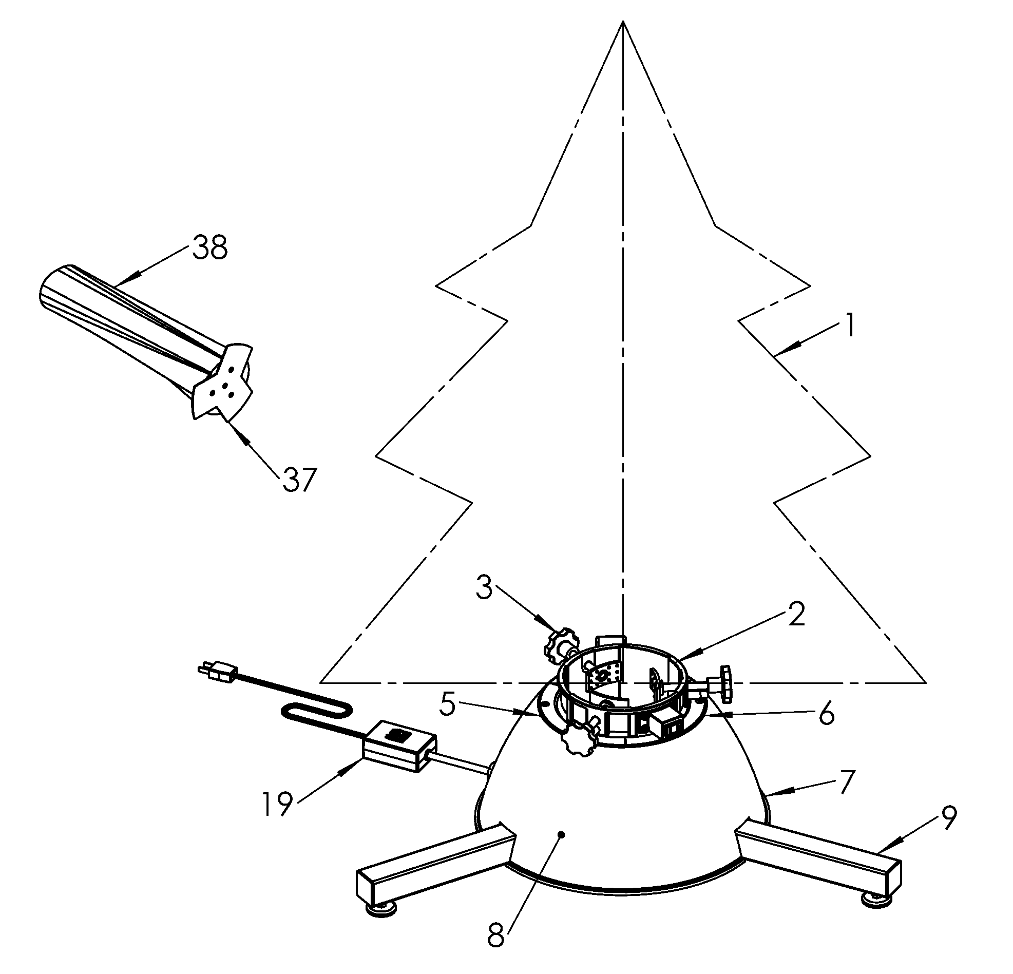
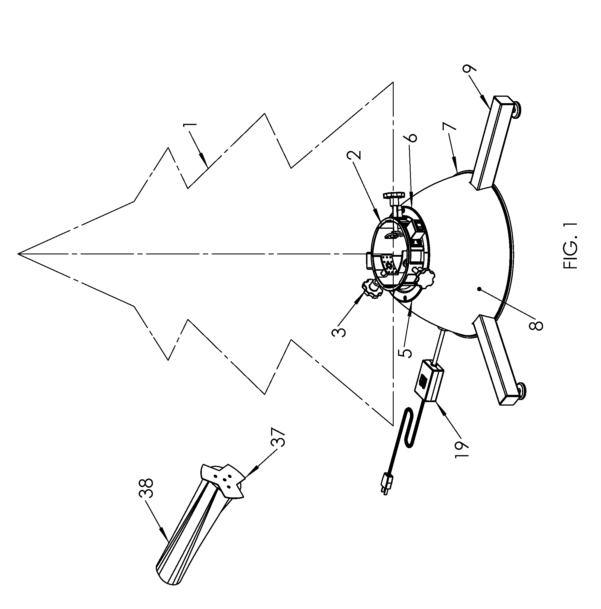
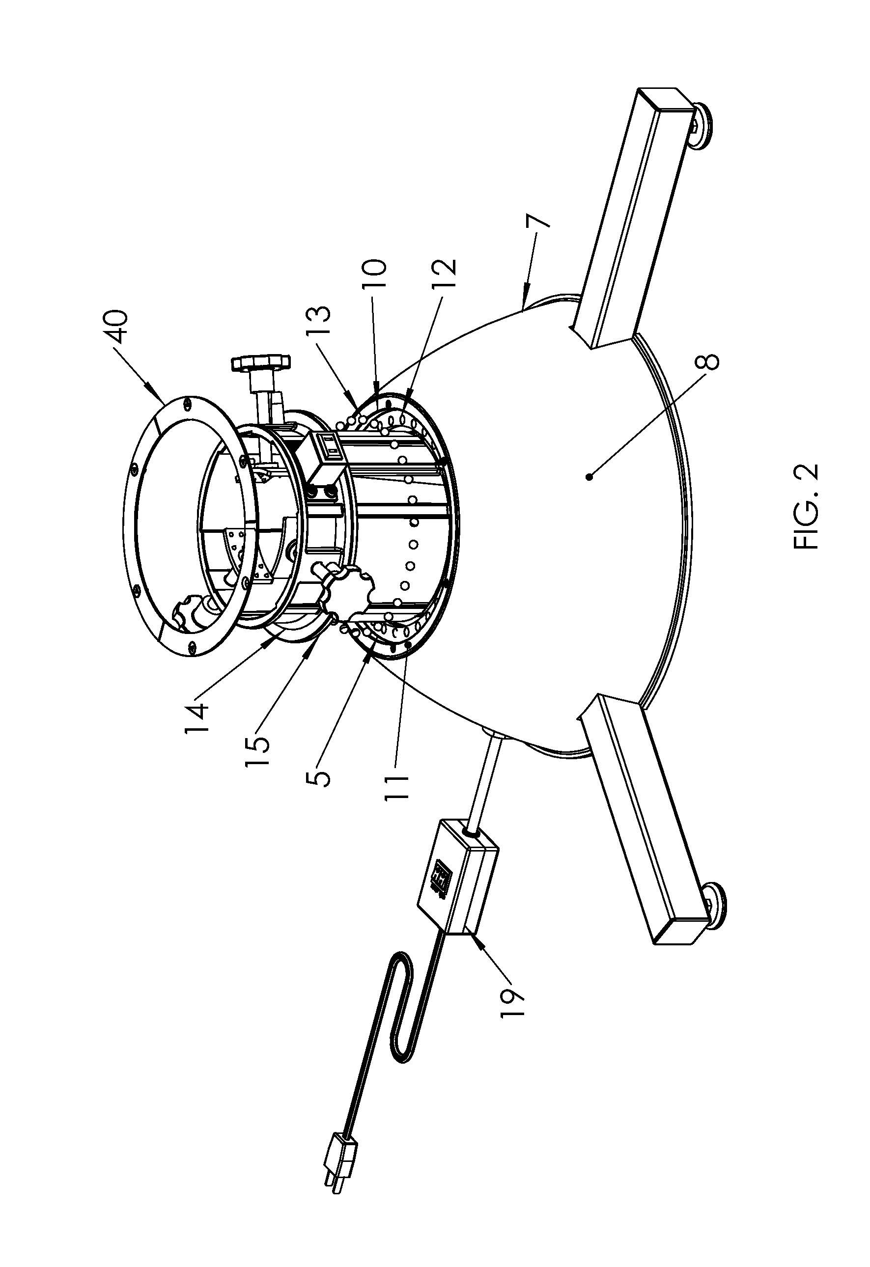
[0018]FIG. 1 shows the general view of a Christmas tree 1 being held onto a rotatable tank assembly 2. A plurality of knob-grippers 3 (see also FIG. 5 and FIG. 6) on top and a Y-shaped plate 37 fastened to the flat cut bottom of the tree section 38 serve to position the tree securely and upright in rotatable tank assembly 2. At the end of each threaded knob-gripper 3 is rotatably attached a curved studded plate 4 (see also FIG. 5 and FIG. 6), designed to substantially match the curvature of a typical Christmas tree trunk, and suitably weighted so as to cause it to be aligned to the axis of the tree truck, even when not in contact with the trunk. The force created by the knob-grippers is transmitted through the gravity aligned curved studded plate, causing the plate to bite into the tree trunk and create a positive, non-slip clamp to retain the heavy, large diameter tree in a substantially upright orientation. The rotatable tank assembly 2 is supported by a support bearing 5, which i...


PUM


Abstract

The present invention provides a Christmas tree stand that is self-watering and rotatable. The self-watering system, that rotates with the tree, mainly includes a water reservoir, a hose, a water tank that holds on to the lower end of the tree, and a valve mechanism that automatically keeps the water in the water tank at optimum level. A rotatable tank assembly is driven by an electric drive motor on a stationary support assembly. Electrical power is passed from the stationary support assembly to the rotatable tank assembly through a slipping-ring connector. In the preferred embodiment, a remote control is provided to supply power for rotation of the rotatable tank assembly, including the tree, and the power receptacle on the rotatable tank assembly for suitable electrical loads, e.g., decorative lights, separately.

Description

FIELD OF THE INVENTION[0001]The present invention relates to a support stand for a plant such as a Christmas tree, and more specifically relates to a support that is rotatable, that has a self-watering system, and that passes the power from the stationary support assembly to the rotatable tank assembly to supply power to the rotatable portion such as decorative lights.BACKGROUND OF THE INVENTION[0002]It has been a challenge to keep Christmas trees alive from the time period starting before Christmas and often ending well after New Year's Day. Many attempts have been made and many patents issued to solve that problem. The design for a rotatable Christmas tree stand presents further challenges to inventors.[0003]U.S. Pat. Nos. 5,979,859 and 6,320,327 requires a slow speed motor, which is less available than a faster motor. U.S. Pat. Nos. 6,128,854, 6,739,566, 6,868,754 and 7021598 solve the problem with speed reduction gear systems to reduce the rate of rotation of a fast motor to a m...

Claims


Application Information

Patent Timeline
Patent Type & Authority Patents(United States)
IPC IPC(8): A47G7/02A47G33/12
CPCA47G33/126A47G2033/122A47G2033/1286A47G2033/1293
Inventor JIN, SAMUEL ZHIHUIADAMSKI, JOSEPH ROBERT
Owner JIN SAMUEL ZHIHUI MR
Learn More