
Fine bubble delivery for potable water, wastewater, and clean water treatment

a technology for potable water and clean water treatment, applied in the direction of pipes, machines/engines, chemical/physical processes, etc., can solve the problems of inability to service aerators that are affixed to the bottom of the body of water, involuntary rollover, and other performance degradation, so as to reduce the risk of puckering or other deformation of the slit, prevent micro-slit deformation, and minimize the lateral curvature of the tubing

Active Publication Date: 2012-03-13
AIR DIFFUSION SYST
View PDF72 Cites 9 Cited by
  • Summary
  • Abstract
  • Description
  • Claims
  • Application Information

AI Technical Summary

Benefits of technology

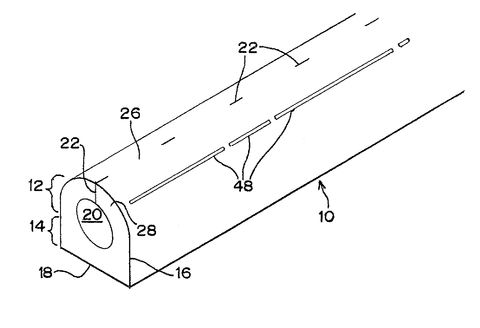
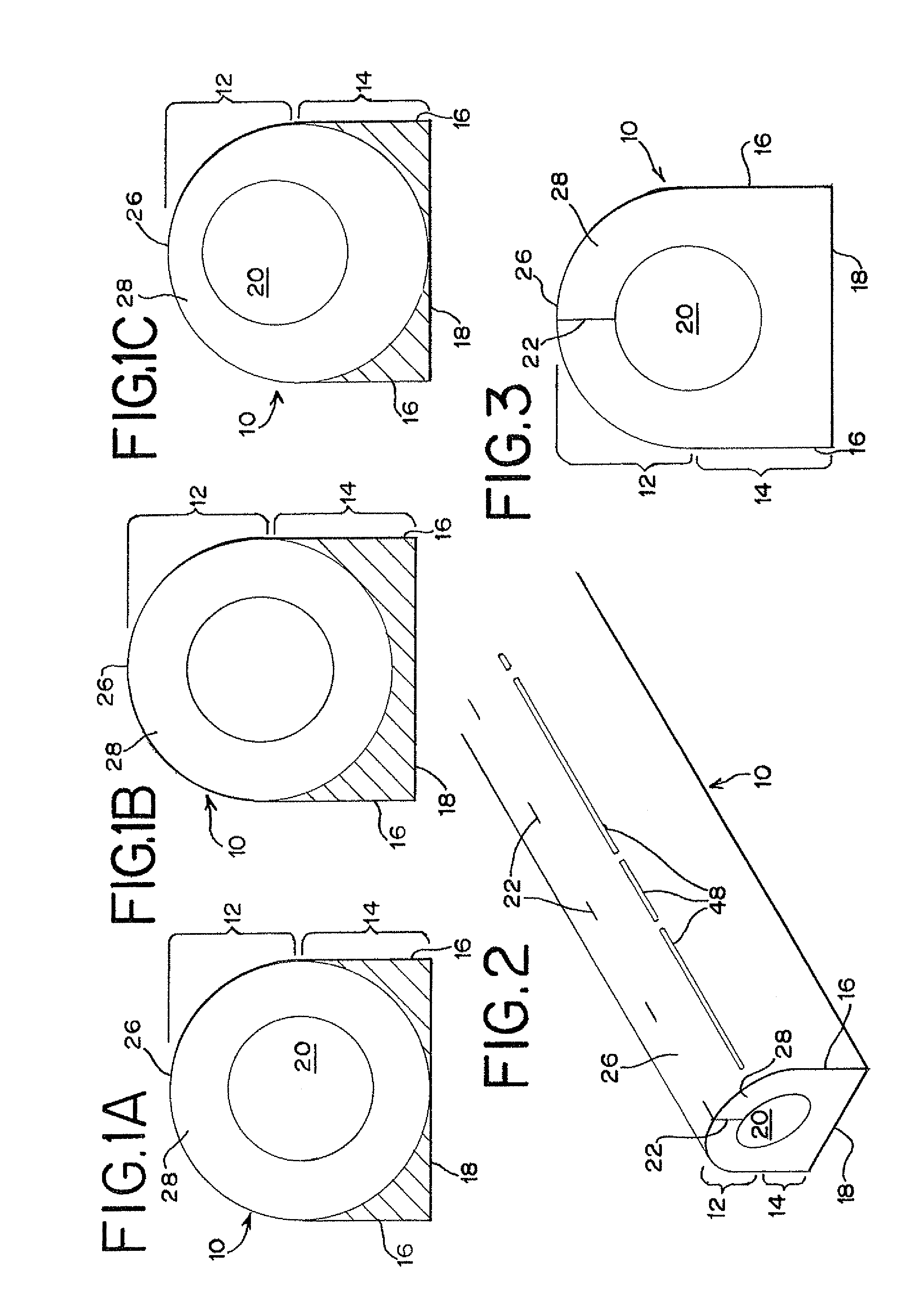
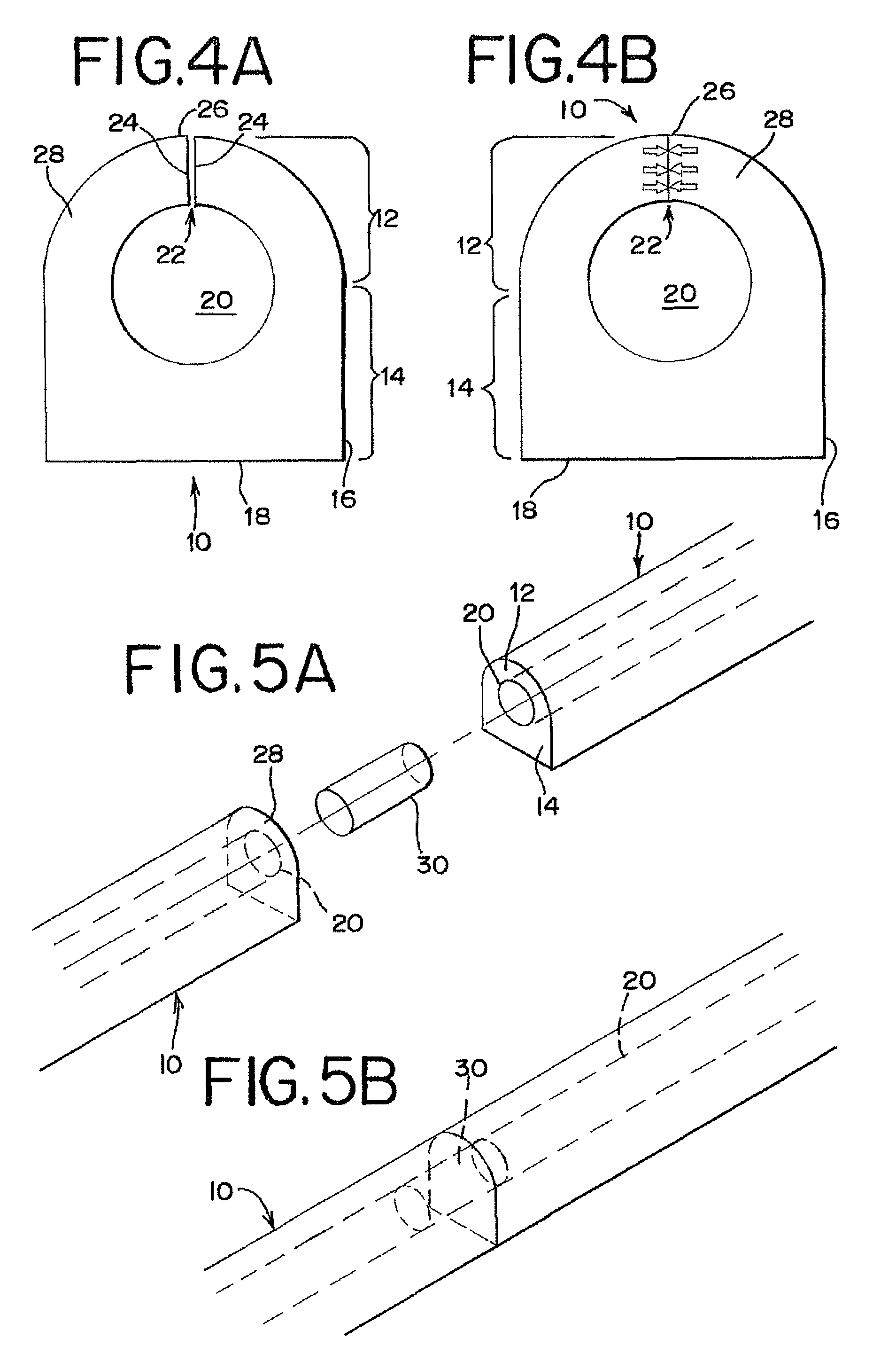
[0021]In accordance with the present invention, a flexible tubing for fine bubble aeration includes an air passageway defined by an upper portion with a larger profile or a widened profile such as a generally arcuate profile and a lower portion with a generally squared profile. The tubing typically is constructed of a substantially uniform mixture of plastics, polymers or rubber-like compounds and a high-density mineral to overcome buoyancy. For example, the rubber-like material may be highly filled vinyl compounds, PVC, polyethylene, polypropylene, polystyrene, or the like, and the high-density material may be barium sulfate or a similar safe dense mineral. Preferably, the mixture allows different lengths of tubing to be glued or fastened together, while the unique larger, widened or heavier lower portion assures proper alignment of the micro-slits when joining separate lengths of tubing.
[0023]Preferably, the tubing walls are relatively thick, with the upper arcuate portion being at least 0.15 inch (3.81 mm) thick and up to 1.50 inches (3.81 cm) thick. The performance of the micro-slits of the upper arcuate portion is enhanced by the thicker wall, which makes the slits more durable and resistant to deformation due to foreseeable use and abuse. The greater thickness also causes an increased pressure differential, typically a minimum internal pressure drop of 2 PSI, which prevents performance degradation in bodies of water having sloped or inclined bottom surfaces.
[0025]The slits are preferably precise, surgical cuts in a straight line along the upper portion of the tubing. The slits are formed without removing any material or leaving any burrs, and the generally rubber-like construction of the tubing imparts an elastic wall memory, so the micro-slits will close tightly when there is no air flowing through the tubing. Thus, the cuts act like check valves to protect themselves and the air passageway from the inflow of debris and settled solids. When combined with a thicker wall, the micro-slits perform even better as check valves and will snap shut after airflow is terminated.
[0026]The tubing is coiled about a spool such that the micro-slits and squared lower portion are each approximately 90° from the spool hub. Thus, there will be no arch along the length of the tubing, which will remain substantially flat, thereby preventing micro-slit deformation, involuntary roll-over, and other performance degradation. Any lateral curvature in the tubing is minimized by soft tension coiling, which reduces the risk of puckering or other deformation of the slits.
[0027]Additional performance and cost benefits of tubing according to the present invention are derived from its simplicity and unique power cost effectiveness. For example, the tubing can biologically convert unwanted wastes in the water into useful biota, carbon dioxide, and pure water with only 1-2% inert ash residual. Also, it is estimated that tubing according to the present invention reduces the costs of operating an associated blower / compressor of systems using this type of tubing to a range of about $0.01 to $0.02 per capita per day for lagoon treatment and to a range of about $0.04 to $0.08 per capita per day for activated sludge treatment.
[0028]The streamlined manufacturing and installation processes, along with the reduced operating costs, are estimated to substantially reduce activated sludge treatment costs. For example, for a small-to-medium sized community (500-10,000 people), such costs can be reduced from a $5-$10 per gallon range to a $1-$2 per gallon range. It will be appreciated that cost reductions are also realized during retrieval and inspection operations due to the durable design according to the present invention.

Problems solved by technology

While these two approaches are effective in properly orienting the tubing, their usefulness is limited for a number of reasons.
Aerators using securing fixtures are generally limited to artificial bodies of water having substantially flat bottoms, in order for the tubing to be properly oriented.
Also, it is very difficult to service aerators that are affixed to the bottom of the body of water.
As for aerators having rigid tubing, they are relatively expensive and, if they are not secured to the bottom of the body of water, then substantial efforts must be taken to ensure that they are submerged at the proper orientation and remain so oriented.
However, flexible tubing according to the prior art is difficult and expensive to manufacture and often results in a great deal of wasted wire material.
The thin wall makes it difficult to achieve and maintain during manufacture, installation and use, an air passageway with a truly circular cross-section, and any resulting tube that is not substantially tubular or has an overly thin or thick wall can be rejected as defective or perform with reduced efficiency.
The wire keel protrusion makes it difficult to properly align the tubing, which can lead to irregularly spaced, sized, and positioned slits.
Furthermore, tubing using a lead ballast wire is even more problematic due to the known harm that lead can cause to the environment and those who handle it.
Another problem with prior art flexible tubing systems is that they generally have a wall thickness no greater than 0.10-0.20 inch (2.54 mm-5.08 mm).
This results in nominal orifice pressure drop, causing uneven air distribution and difficulty controlling bubble size.
Also, it is difficult to adequately clean such tubing systems, because a cleaning solution injected into the tubing will be released through the initial slits, while little or no solution remains in the tubing to reach and clean the slits at a far end of the tubing.
Finally, thin-walled tubing systems are especially prone to kinking, puncturing, collapsing, tearing, cracking, and other performance-inhibiting maladies caused by transport, installation, temperature extremes, high pressure at great submersion depths, abuse by animals, long-term use, and the like.
Yet another possible drawback of using known thin-wall flexible tubing is lifting it from a body of water for inspection or servicing.
Such damage to the tubing degrades the performance of the air-cuts, even if manufactured to provide preferred bubble formation, with a negative result of having the system “boil” air.
When this occurs, the treatment suffers and the tubing needs replacing.

Method used


Image

  • Fine bubble delivery for potable water, wastewater, and clean water treatment
  • Fine bubble delivery for potable water, wastewater, and clean water treatment
  • Fine bubble delivery for potable water, wastewater, and clean water treatment

Examples


Embodiment Construction

[0053]As required, detailed embodiments of the present invention are disclosed herein; however, it is to be understood that the disclosed embodiments are merely exemplary of the invention, which may be embodied in various forms. Therefore, specific details disclosed herein are not to be interpreted as limiting, but merely as a basis for the claims and as a representative basis for teaching one skilled in the art to variously employ the present invention in virtually any appropriate manner.

[0054]FIGS. 1A-4B show several possible embodiments of a flexible tubing 10 according to respective aspects of the present invention. The flexible tubing 10 has an outer cross-sectional profile defined by a substantially semicircular upper portion 12 and a rectangular or squared lower portion 14 having two flat sidewalls 16 extending downwardly from the arcuate upper portion 12 and a flat bottom wall 18 extending between the sidewalls 16. The illustrated tubing cross-section is referred to herein f...


PUM

PropertyMeasurementUnit
thickaaaaaaaaaa
specific gravityaaaaaaaaaa
diameteraaaaaaaaaa

Abstract

A flexible tubing for fine bubble aeration is provided with an air passageway defined in part by an upper portion and a lower portion. The tubing can be made of a uniform weighted material with more material in the lower portion than in the upper portion. This makes the tubing self-orienting, in that it will tend to orient itself with micro-slits along the upper portion facing upward and the lower portion facing downward when submerged in a body of water. An automated, one-stage production line converts raw tubing material to a finished tubing product without the need for separate processing. A method of coiling the tubing places the micro-slits approximately 90° away from the surface of a spool hub, thereby avoiding a longitudinal arch in the tubing and ultimately preventing roll-over and improper slit orientation after installation in a water body.

Description

CROSS REFERENCE TO RELATED APPLICATION[0001]This application claims priority from and the benefit of Provisional Patent Application Ser. No. 60 / 740,355, filed Nov. 29, 2005, which is hereby incorporated herein by reference.BACKGROUND OF THE INVENTION[0002]1. Field of the Invention[0003]This invention generally relates to devices for purification and treatment of bodies of water. More particularly, the invention relates to weighted, flexible tubing which is submerged in a body of water for aeration of the water with small bubbles. Special application is found for this approach in natural bodies of water or in wastewater lagoons which are difficult or impractical to drain.[0004]2. Description of Related Art[0005]Aeration of a body of water is beneficial for a number of reasons. For example, it promotes the growth and survival of aerobic micro-organisms, intermediate life forms such as worms and snails, as well as fish and other aquatic wildlife and prevents ice from forming on docks a...

Claims


Application Information

Patent Timeline
Patent Type & Authority Patents(United States)
IPC IPC(8): B01F3/04B29C48/09B29C48/11B29C48/12
CPCB01F3/04113F16L11/121B26F1/0015B65H54/02B01F3/04269B01F2003/04191B01F2003/04319B01F2003/04368B26F1/20B29C47/003B29C47/0057B29C47/0066B29C47/20B29C2793/0027B29C2793/0036B29C2793/0045B29C2793/0063B29K2021/00B29L2023/005B29L2023/22B65H2701/331B65H2701/3914B29C48/12B29C48/0018B29C48/0022B29C48/32B29C48/09B29C48/11B01F23/23105B01F23/231151B01F23/23124B01F23/231265B01F23/231232Y02W10/10B01F23/231242
Inventor HINDE, JOHN N.
Owner AIR DIFFUSION SYST
Learn More