Facile production of optical communication assemblies and components

a technology of optical communication and assembly, applied in glass making apparatuses, manufacturing tools, instruments, etc., can solve the problems of significant noise or effective signal erosion, limiting technology, and loss of optical performance, so as to reduce the potential for defective linkages, minimize the linkage time, and optimize the effect of performan

Inactive Publication Date: 2012-03-13
CIRREX SYST
View PDF16 Cites 30 Cited by
  • Summary
  • Abstract
  • Description
  • Claims
  • Application Information

AI Technical Summary

Benefits of technology

[0007]Modified fiber interlinks can be manufactured in a separate operation and thus taken off-line from the main optical assembly manufacturing line. These integral interlinks, in which fibers have been shaped so precisely and / or coated with special filters, can be included in optical assemblies to ultimately provide their beneficial functions without slowing the entire assembly operation. This off-line production can result in a subcomponent that minimizes linkage time in the full component assembly operation. The subcomponent also can decrease the potential for defective linkages or less than optimal performance in both the subcomponent manufacturing operation and the assembly operation.

Problems solved by technology

Applicants have found such unwanted photons passing through areas that had not been recognized or had been vastly underestimated as photon passageways potentially creating significant problems.
Applicants have further found the optical performance loss because of these areas to present special, technology limiting problems in applications benefiting from high performance filters.
More specifically, applicants have found that penetration of unwanted photons especially in areas along periphery of the filter layers, even very thin filter layers, can cause significant noise or effective signal erosion.
Problematic optical noise can occur through the filter face itself if, for example, some areas of the filter or the waveguide to which it is optically connected have differing transmission characteristics or demands.

Method used


Image

  • Facile production of optical communication assemblies and components
  • Facile production of optical communication assemblies and components
  • Facile production of optical communication assemblies and components

Examples


Embodiment Construction

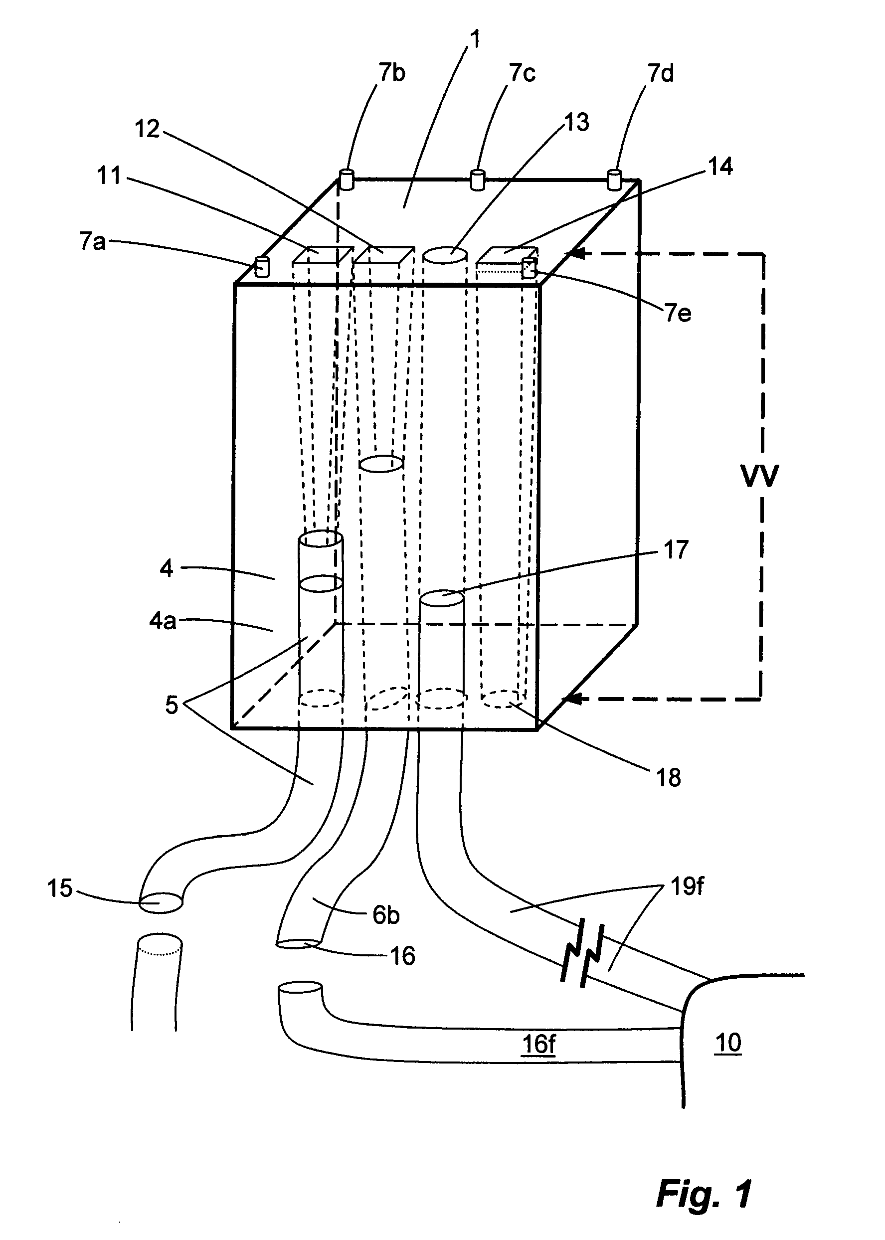
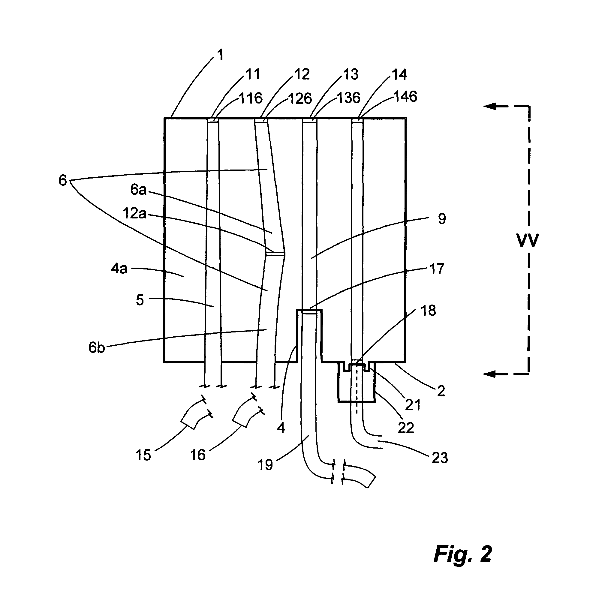
[0034]As shown by the exemplary embodiment in FIG. 1, interlink 4 links by providing optical channels, waveguides 5, 6 (an optical fiber formed by fusing fiber segment 6a to fiber segment 6b forming junction 12a) 8, and 9, between a planar waveguide (see planar waveguide unit 30 in FIG. 3) and at least one optical fiber system 10 of which optical fiber 19f is a part. Optical fiber 19f can be mated to waveguide 9, preferably an optical fiber, at interface 17, by inserting fiber 19f in channel or recess 4c of block 4a (See FIG. 2 for additional detail). For example, by using an appropriate epoxy, fiber 19f can be fused to fiber 9 with a filter disposed at the interface 17 therebetween. Optical fiber 18f can be mated to waveguide 8 at interface 18 by inserting fiber 18f into a locking mechanism 22 such as an optical seal housing. The locking mechanism 22 is coupled to face 2 of the interlink 4 by flanges 21 that engage the locking mechanism 22. Disposed at interface 18 can be a filter....


PUM

PropertyMeasurementUnit
lengthaaaaaaaaaa
angleaaaaaaaaaa
core diameteraaaaaaaaaa

Abstract

A micro identification system supports facile optical assemblies and components. A segment of optical fiber can comprise an identifier formed via actinic radiation. The identifier can generate a laser interference pattern that can be read through a cylindrical surface of the optical fiber to determine a code. Modified optical fibers are those fibers that have been shaped or coated to an extent beyond the demands of normal communications optical fibers. In one example, modified fibers are no longer than about two feet in length. For another example, the modified fibers can have either a non-cylindrical end face, a non flat end face, an end face the plane of which is not perpendicular to the longitudinal axis of the waveguide, an end face coated with high density filter, or an identifier on or near an end face.

Description

CROSS REFERENCE TO RELATED APPLICATIONS[0001]The present application is a continuation of and claims priority to U.S. Non-Provisional patent application Ser. No. 10 / 429,166, entitled “Facile Production of Optical Communication Assemblies and Components” and filed on May 2, 2003 in the name of Wach et al, now U.S. Pat. No. 7,298,936, which is a continuation of and claims priority to U.S. Non-Provisional patent application Ser. No. 10 / 010,854, entitled “Facile Production of Optical Communication Assemblies and Components” and filed on Dec. 4, 2001 now abandoned in the name of Wach et al., which claims priority under 35 U.S.C. 119 to the filing date of Dec. 4, 2000 accorded to the U.S. Provisional Patent Application Ser. No. 60 / 251,270. The entire contents of U.S. Non-Provisional patent application Ser. No. 10 / 429,166 and U.S. Non-Provisional patent application Ser. No. 10 / 010,854 are hereby incorporated herein by reference.BACKGROUND OF THE INVENTION[0002]Fiber to fiber and fiber to w...

Claims


Application Information

Patent Timeline
Patent Type & Authority Patents(United States)
IPC IPC(8): G02B6/34C03C25/00C03B37/018
CPCG02B6/3881G02B6/3652G02B6/30G02B6/12007G02B6/29364G02B6/29367G02B6/29368G02B6/3636G02B6/3644B33Y80/00
Inventor WACH, MICHAEL L.HOLTER, DWIGHT
Owner CIRREX SYST
Why Eureka
Try Eureka