Electronic component mounter and mounting method

a technology for electronic components and mounters, which is applied in the direction of metal working apparatuses, manufacturing tools, instruments, etc., can solve the problems of inability to mount in the right position on the board, board, electronic component or nozzle damage, and discrepancy between the actual height of the component and the entered data, so as to achieve accurate height measurement and small measurement range

Active Publication Date: 2012-03-20
PANASONIC CORP
View PDF27 Cites 6 Cited by
  • Summary
  • Abstract
  • Description
  • Claims
  • Application Information

AI Technical Summary

Benefits of technology

[0009]So, the present invention has been conceived in view of the above problems, and it is an object of the present invention to provide a method for accurately measuring the heights of a variety of components ranging from tiny components to larger ones, using a sensor with a small measurement range.
[0011]Accordingly, since the height of the component is measured after the component is lowered to within the high-accuracy range of the sensor, the height can be measured accurately.
[0013]Accordingly, since the height of the component is measured based on the amount of lowering of the nozzle and the signal outputted from the sensor, it is possible to measure the heights of various components ranging from tiny components to larger ones, even if a sensor is relatively small. In addition, even using a sensor having variable accuracy from one position to another, it is possible to ensure high measurement accuracy by measuring the component twice.
[0015]Accordingly, for a mounter in which a nozzle needs to be replaced, it becomes possible to avoid having an influence of dimensional accuracy or attachment accuracy of the nozzle on the measured value of the component height as much as possible.
[0017]Accordingly, when the height of a relatively thin component is measured, the repetitive error of the nozzle, rather than the lowering error thereof, has a greater influence on the measured value of its height. On the contrary, as for a relatively thick component, the lowering error of the nozzle has a greater influence on the measured value of its height. When the repetitive error is smaller than the lowering error, it is possible to lower the probability of occurrence of significant errors in the component height.
[0022]According to the present invention, it is possible to measure the heights of a variety of components ranging from tiny components to larger ones, using a high-accuracy portion of a small sensor, and therefore it is possible to detect the heights of electronic components with a high degree of accuracy.

Problems solved by technology

To be more specific, if the actual height of an electronic component held by a transfer head for mounting it is different from a value assigned to the electronic component and stored for controlling the mounter, various types of problems occur when mounting the electronic component onto a board.
For example, in the case where the actual height of an electronic component is less than the stored data, the electronic component is released before it reaches the board, and thus it may not be mounted in the right position on the board.
Conversely, if the actual height of an electronic component is greater than the stored data, the electronic component is pressed against the board too strongly that the board, the electronic component or the nozzle may be damaged.
Such data entry is not only very troublesome but also causes measurement error or human error in the case where the height of a substitute component is measured and the data of the component is entered manually, and thus causes a discrepancy between the actual height of the component and the entered data.
If a detector for detecting the size, in particular, the height of a component, is applied to such a multifunction mounter, the following problems occur.
If such a detector is attached to the transfer head of the mounter, the size and weight of the detector burden the transfer head which moves at a high speed to mount components, and thus the positioning accuracy of the transfer head cannot be maintained.
Furthermore, since a large-sized detector has generally a low resolution, if this detector measures the height of a tiny component, the measurement error for the height is too large to mount the component without any problem.
A large-sized detector with a high resolution unnecessarily leads to rise in cost.

Method used


Image

  • Electronic component mounter and mounting method
  • Electronic component mounter and mounting method
  • Electronic component mounter and mounting method

Examples


first embodiment

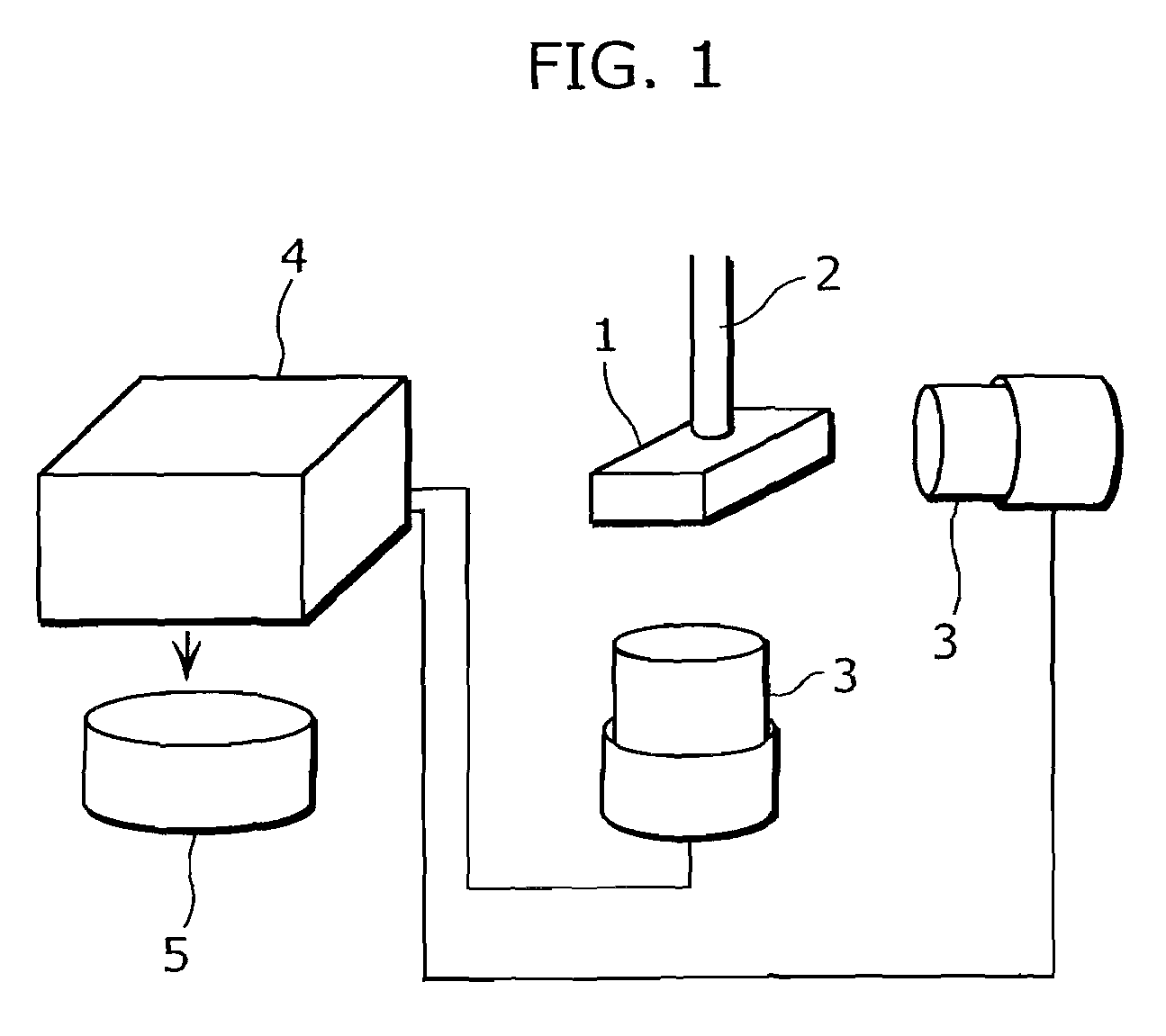
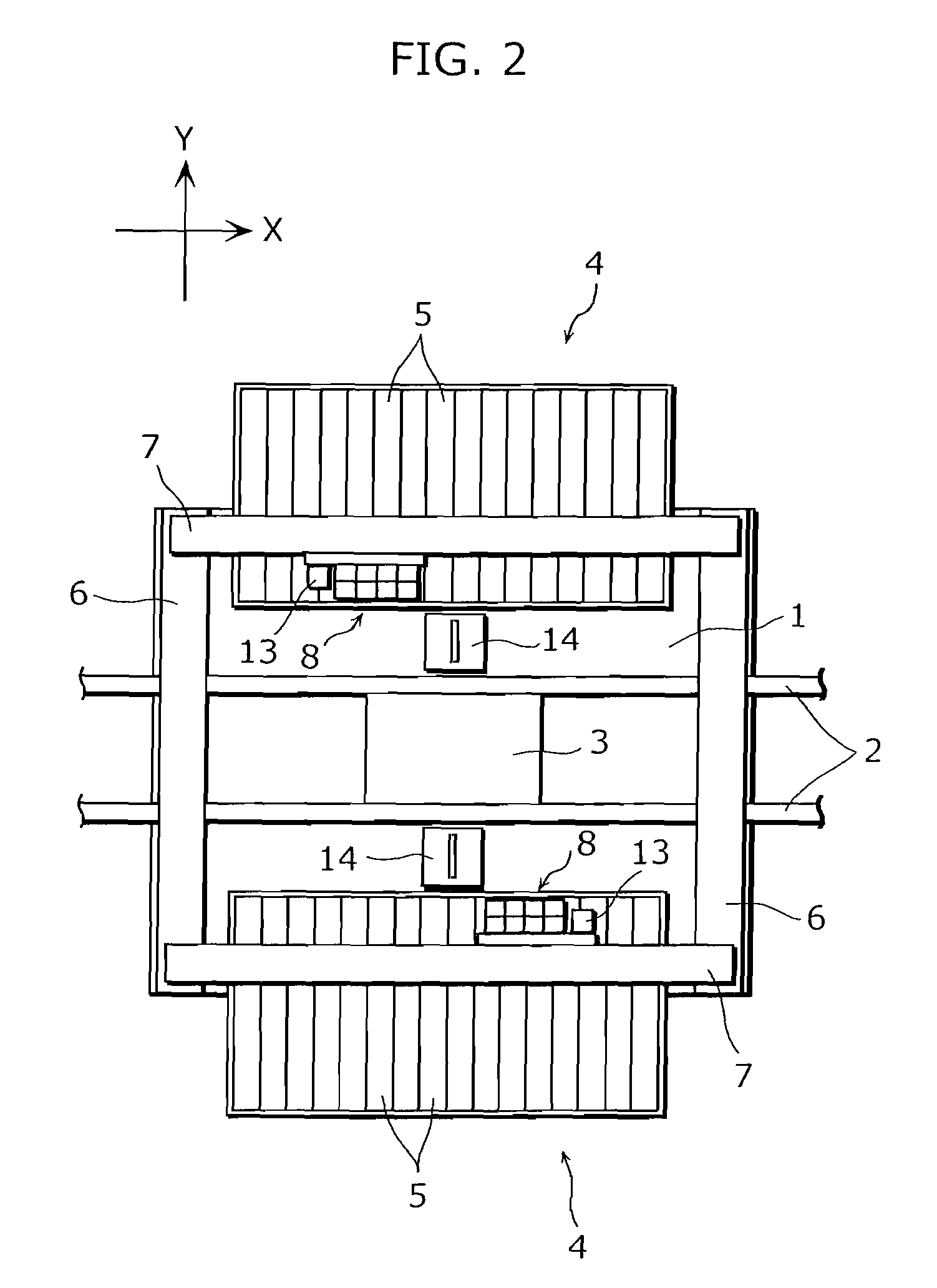
[0052]Next, an embodiment of the present invention is described with reference to drawings. FIG. 2 is a plan view of an electronic component mounter in one of the embodiments of the present invention; FIG. 3A is a front view of a transfer head of the electronic component mounter in one of the embodiments of the present invention; FIG. 3B is a side view of the transfer head of the electronic component mounter in one of the embodiments of the present invention; FIG. 4 is a configuration diagram of the control system of the electronic component mounter in one of the embodiments of the present invention; FIG. 5 is a diagram for explaining a method for detecting electronic components in one of the embodiments of the present invention; and FIG. 6 is a flowchart of an operation sequence of the electronic component mounter in one of the embodiments of the present invention.

[0053]First, an overall configuration of an electronic component mounter is described with reference to FIG. 2, FIG. 3A...

second embodiment

[0066]Next, another embodiment of the present invention is described.

[0067]The object of the second embodiment is as follows.

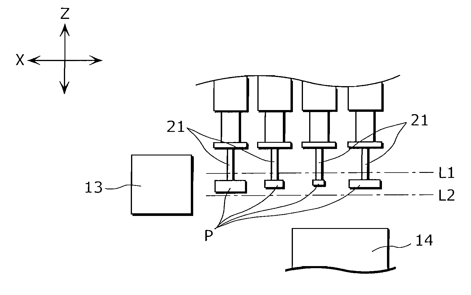
[0068]According to the method described in an already disclosed patent reference (Japanese Laid-Open Patent Application No. 2002-09496 Publication), the mounting surfaces of components P sucked and held by respective nozzles 21 are aligned with the level of the focus position of the second line sensor 14, regardless of the heights of respective components P, and therefore the levels of the nozzles 21 are adjusted so as to be the levels obtained by subtracting the heights of respective components P from the level of the focus position. More specifically, the level of each nozzle 21 is managed by an absolute value. The level of each nozzle 21 is adjusted by coupling the nozzle 21 with a nut screwed with a ball screw and controlling the axial rotation of this ball screw. Therefore, the error caused by machining accuracy of the ball screw has a direct impact on th...

third embodiment

[0083]Next, a method for detecting components by the first line sensor 13 and the second line sensor 14 is described with reference to FIG. 7. In the present embodiment, components to be mounted are classified into first components and second components, and the first components and the second components are respectively detected by different detection methods. Note that the configuration of the electronic component mounter in the present embodiment is same as that in the above first and second embodiments.

[0084]In the present embodiment, the first components are tiny components such as 0402, 0603 and 1005 chip capacitors, and they have minute differences in size such as length, width, height, oblique length and the like. Such tiny components further include 1608R and 2625R chip capacitors and other chip components which do not have such minute differences in size but have the heights of 0.5 mm or less. On the other hand, the second components are relatively large components which a...


PUM

PropertyMeasurementUnit
heightsaaaaaaaaaa
lengthaaaaaaaaaa
lengthaaaaaaaaaa

Abstract

A method by which the height of an electronic component sucked and held by a nozzle can be detected with high accuracy and high efficiency is a component height measurement method applied to a mounter (100) equipped with a transfer head (8) having a component-sucking-and-holding nozzle (21), for transferring a component P and mounting the component P onto a board (3), and includes: lowering the component P to within the high-accuracy range of a first line sensor (13) for measuring the height of the component P; and measuring the height of the component P using the first line sensor (13).

Description

TECHNICAL FIELD[0001]The present invention relates to a method for measuring the height (thickness) of a component which is picked up by suction with a nozzle of a mounter and mounted onto a member such as a board and the like.BACKGROUND ART[0002]The height of an electronic component to be mounted is one of the important parameters for a mounter. To be more specific, if the actual height of an electronic component held by a transfer head for mounting it is different from a value assigned to the electronic component and stored for controlling the mounter, various types of problems occur when mounting the electronic component onto a board. For example, in the case where the actual height of an electronic component is less than the stored data, the electronic component is released before it reaches the board, and thus it may not be mounted in the right position on the board. Conversely, if the actual height of an electronic component is greater than the stored data, the electronic comp...

Claims


Application Information

Patent Timeline
Patent Type & Authority Patents(United States)
IPC IPC(8): H05K13/04
CPCH05K13/04Y10T29/53174Y10T29/49004Y10T29/53191Y10T29/49131H05K13/0409H05K13/0413
Inventor ENDO, TADASHINOUDO, AKIRAKAWASE, TAKEYUKIOKUDA, OSAMUOGATA, HIROSHI
Owner PANASONIC CORP
Why Eureka
Try Eureka