Cutting tool

a cutting tool and cutting blade technology, applied in the field of cutting tools, can solve the problems of increased cutting movement, inefficient cutting operation, increased cutting movement of the handle, etc., and achieve the effect of saving manufacturing costs and less expensiv

Active Publication Date: 2012-03-20
FISKARS BRANDS FINLAND
View PDF114 Cites 25 Cited by
  • Summary
  • Abstract
  • Description
  • Claims
  • Application Information

AI Technical Summary

Benefits of technology

[0011]An advantage of the method and system according to the invention is that the transmission means do not have to be provided in the cutting blades, which means that they may be manufactured from a material less expensive than metal, e.g. from plastic or another castable material. In addition, it is possible to integrate the transmission means, i.e. the toothed transmission means, excluding a separate engagement part, into the handle, so that no separate parts are needed for these transmission means. In such a case, the number of parts of the cutting tool can be kept to a minimum, which further saves manufacturing costs.

Problems solved by technology

As the cutting movement progresses, most branches are cut using the outermost ends of the cutting blades, which is disadvantageous since at the outermost end of the cutting blades the cutting power is the lowest.
This results in inefficient cutting operation.
Hence, the cutting movement is inefficient, since the process of gathering the branches inside the sector defined by the cutting blades requires considerably less power than that of actually cutting the branches.
This often leads to an increased movement of the handles, which compels the user to take a wider grip than would otherwise be necessary.
A problem with the above-described arrangement is that at least one of the transmission means are formed directly in a blade, which means that they are made of the same material as the blade.
It is a laborious procedure to work metal in order to provide such transmission means and, besides, metal is an expensive material, so transmission means, and thus hedge shears, are expensive to manufacture.
Furthermore, transmission means formed directly in the blade easily allow branches to enter between the teeth of the transmission means during the cutting operation, which hinders or even prevents operation of the hedge shears.

Method used


Image

  • Cutting tool
  • Cutting tool
  • Cutting tool

Examples


Embodiment Construction

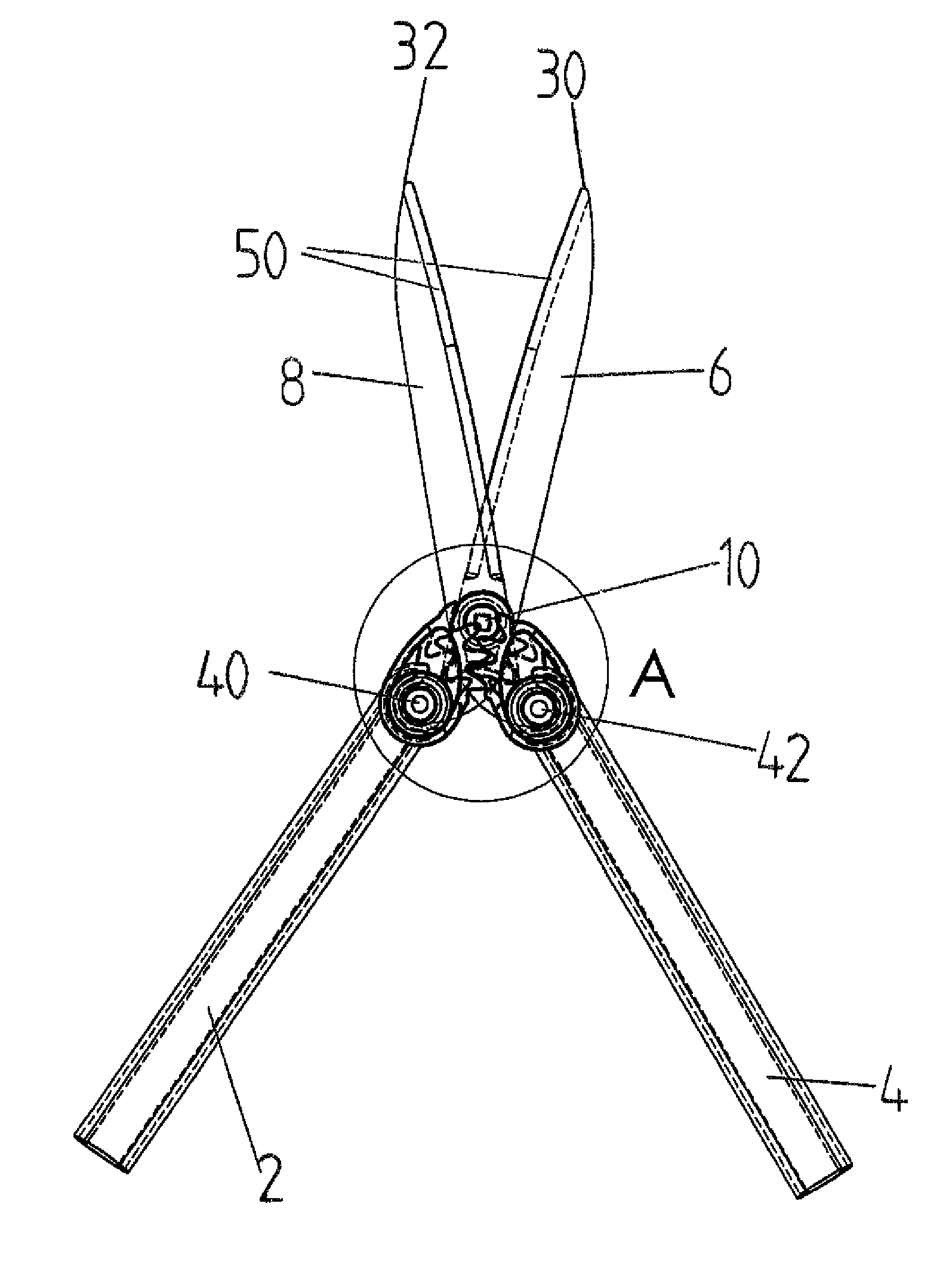
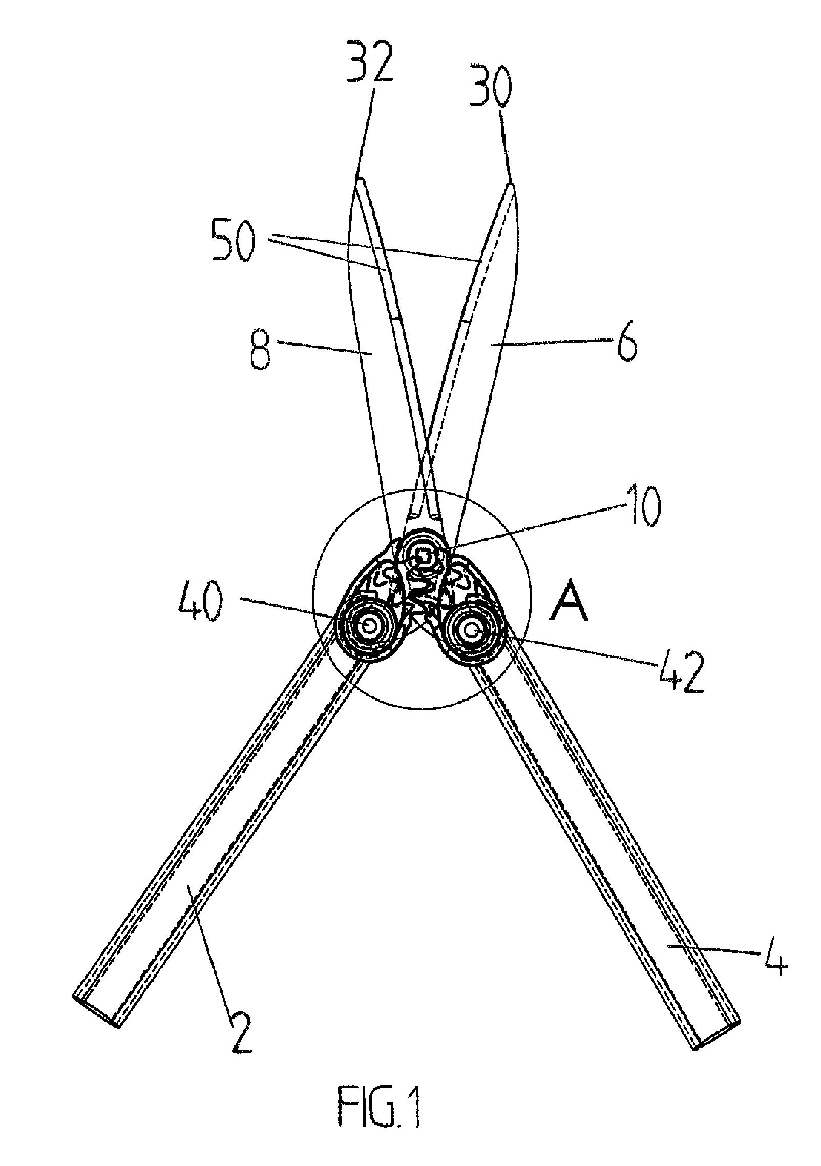
[0015]FIG. 1 shows an embodiment of a cutting tool according to the present invention, which in this embodiment is hedge shears. These hedge shears comprise a first handle 2 and a second handle 4. The handles are generally straight, elongated parts and they may be made of steel, plastic, aluminium or any other material widely known in the art. Furthermore, the handles may comprise, preferably at their ends, a grip part which may be designed to fit the user's hand and provided with a friction-enhancing material, such as rubber. The hedge shears further comprise cutting blades 6 and 8, which are preferably made of steel or aluminium or another suitable material known in the art. The cutting blades 6 and 8 further comprise cutting edges 50.

[0016]According to FIG. 1, the first cutting blade 6 is attached to the first handle 2 at a first pivot point 40 and the second cutting blade 8 is attached to the second handle 4 at a second pivot point 42. The cutting blades 6 and 8 are thus pivotal...


PUM


Abstract

A cutting tool includes a first handle, a second handle, a first cutting blade attached to the first handle at a first pivot point, and a second cutting blade attached to the second handle at a second pivot point. The first and the second cutting blades are engaged with one another at a pivot point for movement in a scissor-like manner between an open position and a closed position in response to rotational movement of the first and the second handles. The first handle includes a first toothed transmission part and the second handle includes a second toothed transmission part, the first and the second toothed transmission parts being arranged to be engaged with one another.

Description

[0001]This application is a United States National Phase of International Patent Application No. PCT / FI2007 / 050255 filed May 8, 2007 which claims priority to Finland Application No. 20065304 filed May 9, 2006, the disclosures of which are hereby incorporated by reference in their entirety.BACKGROUND OF THE INVENTION[0002]The invention relates to a cutting tool according to claim 1, and particularly to a cutting tool comprising a first handle, a second handle, a first cutting blade fixedly attached to the first handle, as well as a second cutting blade fixedly attached to the second handle, the first and the second cutting blades being engaged with one another at a pivot point such that the first and the second cutting blades are movable in a scissor-like manner between an open position and a closed position in response to a relative rotational movement of the first and the second handles around the pivot point, and transmission means for transmitting power from the handles to the cu...

Claims


Application Information

Patent Timeline
Patent Type & Authority Patents(United States)
IPC IPC(8): B26B17/02
CPCB25B7/12A01G3/0475B26B13/26A01G3/02B26B17/02
Inventor LINDEN, OLAVIPALOHEIMO, MARKUS
Owner FISKARS BRANDS FINLAND
Why Eureka
Try Eureka