Arrangement, device and method at a disturbance-eliminating valve for damper

a technology of disturbance-eliminating valves and dampers, applied in the field of damper arrangements, can solve the problems of not solving the problem in a correct way, the damage relating to the function of the valve on the low pressure side can be lost, and the sound is particularly irritating to the human ear, so as to achieve the effect of avoiding damage and avoiding damag

Active Publication Date: 2012-03-20
OHLINS
View PDF4 Cites 23 Cited by
  • Summary
  • Abstract
  • Description
  • Claims
  • Application Information

AI Technical Summary

Benefits of technology

[0014]Certain features, aspects and advantages of some embodiments of the present invention also relate to a method for eliminating disturbances caused by the admixture of gas in a damping medium in a partial step valve or pilot valve arranged in a vehicle.
[0015]The valve described above is able to operate silently and is believed to be completely unaffected by gas that is saturated in the oil in shock absorbers. In addition, the main stage of the valve can be provided with a double spring function that makes it possible to carry out very accurately set and low preloading with small variations in spite of the selection of a stiff spring constant. The whole valve can be assembled in sequence from one direction.
[0017]The principal characteristic of an arrangement according to certain features, aspects and advantages of some embodiments of the present invention is, among other things, that the first piston is located on a valve slide that can move in a longitudinal direction and that extends into the first space and into a second space in the housing that is connected to the first space. In addition, a control edge for the valve slide is located at a transition to the second space, while at the same time the part of the slide that extends into the second space has an extension part upstream of the control edge with a second piston arranged on the extension part. The second piston divides the second space into third and fourth partial spaces. These partial spaces divide the area of action of the valve slide into a first part in association with the seat or control edge and a second part on the underside of the second piston. In addition, certain features, aspects and advantages of some embodiments of the present invention are characterized in that the second piston and an opposing inner guide face in the second space are arranged with a clearance between them that eliminates disturbance by ensuring that the pressure differences that arise in the second space (i.e., the cavity) at the second piston as a result of the speed of movement of the slide affect the second part of the area of action of the slide with a force that counteracts the movement.
[0019]The valve thus works with damping on the high pressure side, that is upstream, which helps to solve the problem discussed above.
[0021]The device according to the invention can also be said to be characterized in that, in a stationary control position of the body, the pressure in the damping chamber is arranged to assume a value that essentially corresponds to a pressure value in the pilot pressure chamber, in that, in the event of an urged movement from the stationary control position, the body is arranged to bring about a pressure difference at the part and in that, in the event of the movement, the pressure in the damping chamber undergoes a change in value that is essentially proportional to the speed of movement of the body and generates a damping force that coincides with the control force and that counteracts the movement of the body and thereby brings about the disturbance elimination, that can consist of preventing any admixture of gas in the medium affecting damping caused by the valve or preventing unwanted noises arising due to the admixture of gas.

Problems solved by technology

The problem with the valves in these references is that their damping is based on the sum of hydraulic damping in the solenoid or in its vicinity, and friction.
This means that the damping that relates to valve functions on the low pressure side can be lost under the circumstances.
Remaining friction is insufficient to damp the valve function, which can cause oscillations with frequencies within the range 400-1500 Hz.
This sound is particularly irritating to the human ear and is not acceptable to car users and car manufacturers.
Increased friction has been tested and has been found not to solve the problem in a correct way.

Method used


Image

  • Arrangement, device and method at a disturbance-eliminating valve for damper
  • Arrangement, device and method at a disturbance-eliminating valve for damper
  • Arrangement, device and method at a disturbance-eliminating valve for damper

Examples


Embodiment Construction

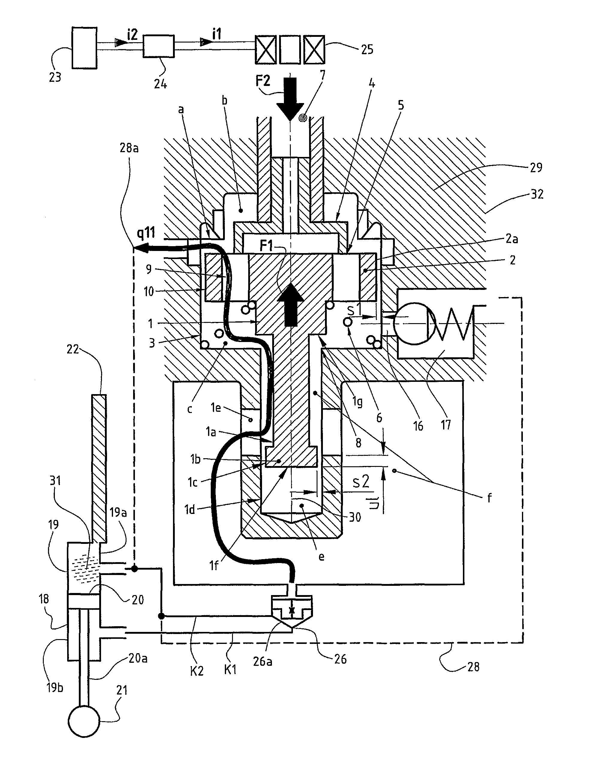
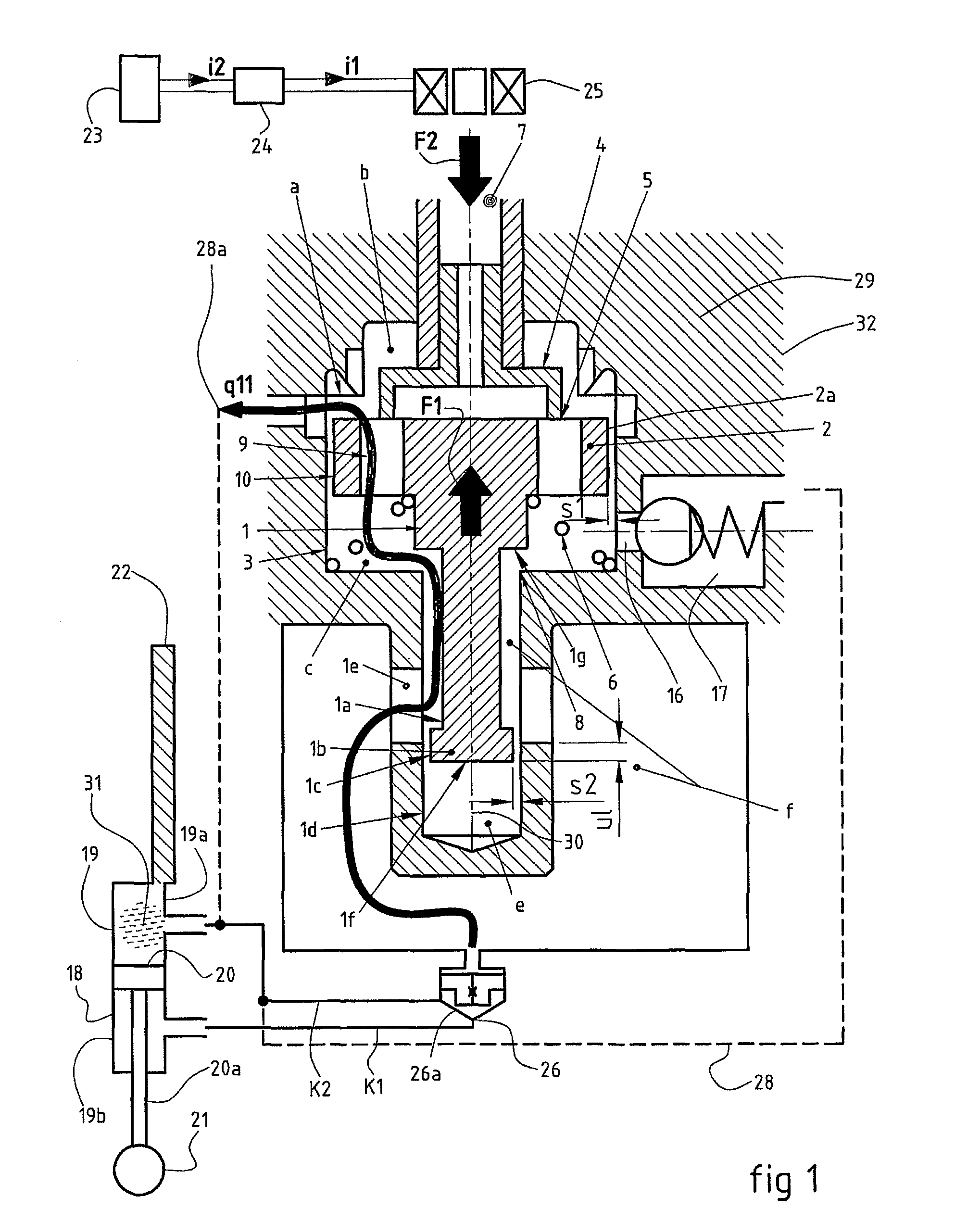
[0039]FIG. 1 shows the arrangement / valve with an activated valve actuator and FIG. 2 shows the arrangement / faces towards the actuator provided with a disk-shaped first piston 2, which is guided against valve in deactivated state. A valve piston 1 is on a part that an inner wall 3 of the pilot housing and which makes contact in an axial direction with an actuator pin 4 in a plane 5 perpendicular to the direction of movement.

[0040]The valve piston 1 of the pilot valve is acted upon in one direction by a first force F1 from a spring 6 or a device exerting a biasing force and by forces that result from pressure exerted in the chambers e and f. The valve piston 1 also is acted upon in a second direction by a second force F2 from an actuator 7 in the activated state. The pilot cone is normally located several hundredths from a control edge 8.

[0041]In its extension, the valve piston 1 is provided with an extension part 1a and a second piston 1b. A guide face 10 of the second piston 1b pref...


PUM


Abstract

An electronically-controlled damper arrangement includes a valve assembly. The valve assembly features a valve slide that carries at least two pistons. The first piston controls flow through two separate flow paths while the second piston controls damping provided by the valve slide. The first piston being both axially moveable and radially moveable within a valve housing.

Description

CROSS-REFERENCE TO RELATED APPLICATION[0001]This application claims the benefit and priority to and is a U.S. National Phase of PCT International Application Number PCT / SE2006 / 000701, filed on Jun. 14, 2006, designating the United States of America and published in the English language, which claims priority under 35 U.S.C. §119 to Swedish Application Number 0501345-3, filed on Jun. 14, 2005. The disclosures of the above-referenced applications are hereby expressly incorporated by reference in their entireties.BACKGROUND OF THE INVENTION[0002]1. Field of the Invention[0003]The present invention generally relates to damping arrangements, such as dampers used in shock absorbers or steering assemblies, used in motor vehicle applications. More particularly, the present invention relates to a valve assembly used with such dampers that operates to remove undesired oscillations during use caused by an admixture of air and damper medium.[0004]2. Description of the Related Art[0005]The techn...

Claims


Application Information

Patent Timeline
Patent Type & Authority Patents(United States)
IPC IPC(8): F16F9/34
CPCB60G17/056B60G17/08F16F9/512F16F9/466F16F9/341F16F9/465F16F9/50
Inventor SONSTEROD, LARS
Owner OHLINS
Why Eureka
Try Eureka