Auger conveyer

a conveyer and auger technology, applied in the direction of shaft and bearings, packaging, rotary bearings, etc., can solve the problems of reducing the life of components, causing operational problems, and affecting the service life of auger conveyors

Inactive Publication Date: 2012-03-20
AG GROWTH IND INC
View PDF11 Cites 15 Cited by
  • Summary
  • Abstract
  • Description
  • Claims
  • Application Information

AI Technical Summary

Problems solved by technology

Some auger conveyors have a considerable length that can create operational issues under certain circumstances.
Misalignment further results in reduced component life due to wear and abrasion, unsafe work conditions, and products contaminated by the worn components.
Most auger conveyors are designed, however, such that lengthy and laborious disassembly and reassembly is required to remove the auger screw from the conveyor housing.

Method used


Image

  • Auger conveyer
  • Auger conveyer
  • Auger conveyer

Examples


Embodiment Construction

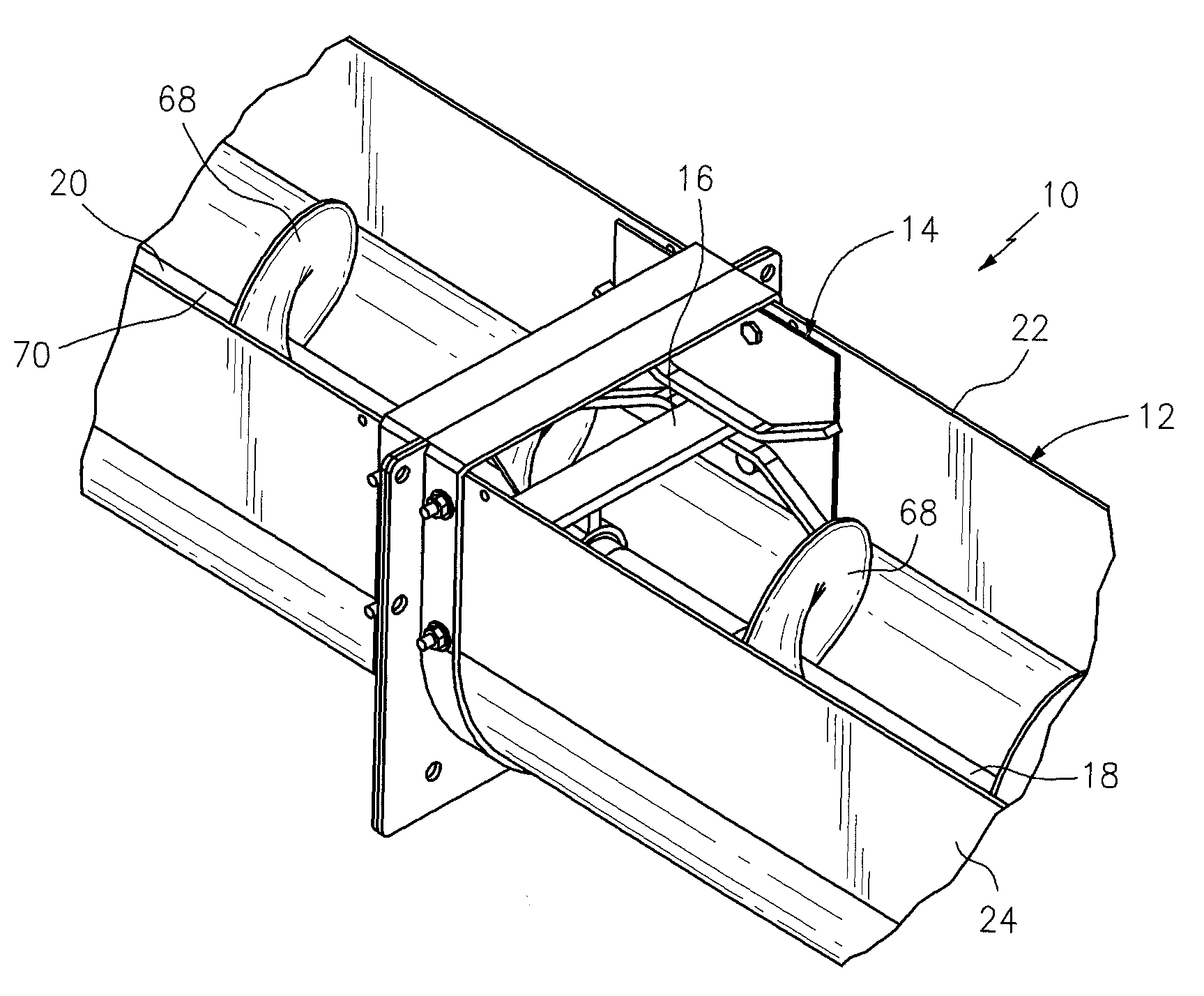
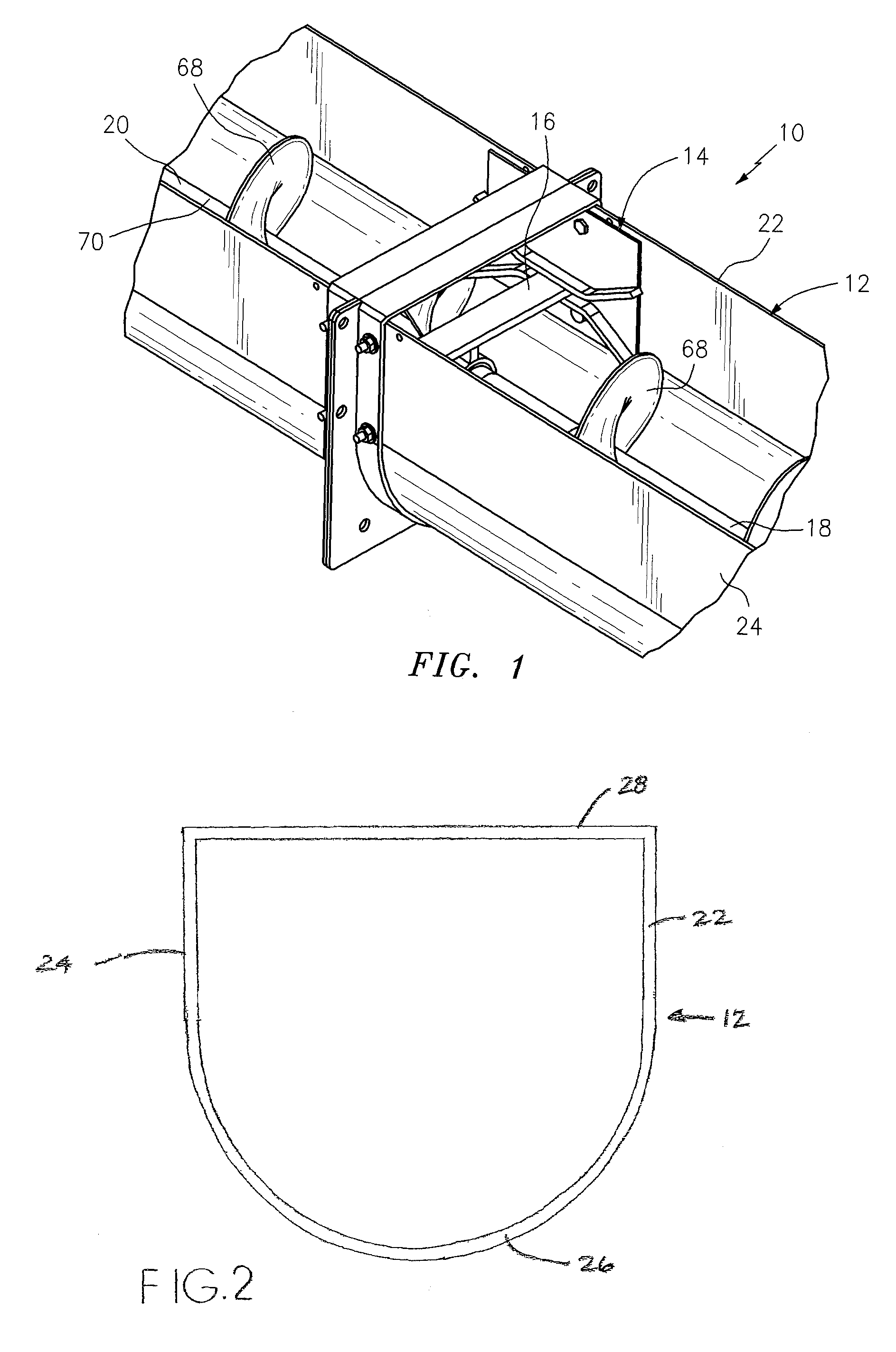
[0019]FIG. 1 is a diagrammatic illustration of one embodiment of an auger conveyor 10. The auger conveyor 10 includes a conveyor housing 12, at least one mounting bracket 14, at least one auger support assembly 16, and an auger screw that includes a plurality of auger screw sections 18, 20.

[0020]Referring to FIGS. 1, 2, 6 and 7, the conveyor housing 12 has a first side 22, a second side 24, a base 26, and a top 28. The conveyor housing 12 extends longitudinally between an inlet 27 and an outlet 29. The inlet 27 and outlet 29 of the conveyor housing 12 can have any geometry that permits the bulk material to enter into the auger conveyor 10 and be moved out of the auger conveyor 10, respectively. The conveyor housing 12 illustrated in FIGS. 1, 2, 6 and 7 has a “U-shaped” cross-sectional geometry extending longitudinally between the first end 23 and the second end 25. The invention is not limited to a U-shaped geometry, however. As is shown in FIG. 6, the auger conveyor 10 is engaged w...


PUM


Abstract

An auger conveyor is provided that includes a housing, at least one first mounting bracket, at least one second mounting bracket, an auger screw and one or more auger support assemblies. The first mounting bracket has a first landing and the second mounting bracket has a second landing. The first and second mounting brackets are attached to the housing at positions diametrically opposite one another. The auger screw has a rotational axis. The one or more auger support assemblies each have a lateral member connected to a bushing assembly. The auger screw is rotatably mounted relative to the bushing assembly. First and second ends of the lateral member each have a geometry adapted to slidably engage with the first landing and the second landing, respectively. The auger screw and the one or more auger support assemblies are adapted to be received within and removed from the housing as an assembled unit, by insertion / removal through the first end of the housing.

Description

[0001]Applicant hereby claims priority benefits under 35 U.S.C. §119(e) of U.S. Provisional Patent Application No. 61 / 251,928 filed Oct. 15, 2009, the disclosure of which is herein incorporated by reference.BACKGROUND OF THE INVENTION[0002]1. Technical Field[0003]This disclosure relates to auger conveyors in general, and to auger conveyors engaged with a storage silo in particular.[0004]2. Background Information[0005]Auger conveyors can be used to convey rice, grain and other bulk material, to load and unload storage silos, and to feed processing equipment. Auger conveyors typically include a helical auger screw disposed within a housing or trough. In operation, the auger screw rotates about its longitudinal axis to convey material along the length of the conveyor. A bearing assembly at one end of the conveyor and a drive assembly at the other end of the conveyor enable the auger screw to rotate within the housing.[0006]Some auger conveyors have a considerable length that can create...

Claims


Application Information

Patent Timeline
Patent Type & Authority Patents(United States)
IPC IPC(8): B65G33/32
CPCB65G33/00B65G33/30B65G33/32
Inventor MORELAND, BRIAN S.MILLER, BRADLEY A.WHITESEL, JAMIE R.BRIM, R. DUANE
Owner AG GROWTH IND INC
Why Eureka
Try Eureka