Connector for preventing terminal insertion in the terminal insert hole

a technology of connecting rods and terminals, applied in the direction of connecting rods, electrical devices, coupling devices, etc., can solve the problems of more difficult to recognize the directional performance or orientation of the terminal during the insertion of the terminal, and not only for the square terminal, but also for the square terminal

Active Publication Date: 2012-03-20
YAZAKI CORP
View PDF7 Cites 4 Cited by
  • Summary
  • Abstract
  • Description
  • Claims
  • Application Information

AI Technical Summary

Benefits of technology

[0011]The present invention is devised by considering the above-described circumstances, and it is an object of the present invention to provide a connector that can simply unify the directional performance of a terminal by using a round terminal even when the terminal is miniaturized or has multi-poles

Problems solved by technology

However, with the progress of a miniaturization of the connector, when the terminal is designed to be miniaturized, as the terminal is smaller, it is the more difficult to recognize the directional performance or orientation of the terminal during the insertion of the terminal.
However, when the terminal is miniaturized, it is very difficult not only for the square terminal, but also for the round terminal to recognize the directional performance or orientation and attach the terminal to the connector housing at the same time.

Method used


Image

  • Connector for preventing terminal insertion in the terminal insert hole
  • Connector for preventing terminal insertion in the terminal insert hole
  • Connector for preventing terminal insertion in the terminal insert hole

Examples


Embodiment Construction

[0048]Now, an exemplary embodiment of the present invention will be described below by referring to the drawings.

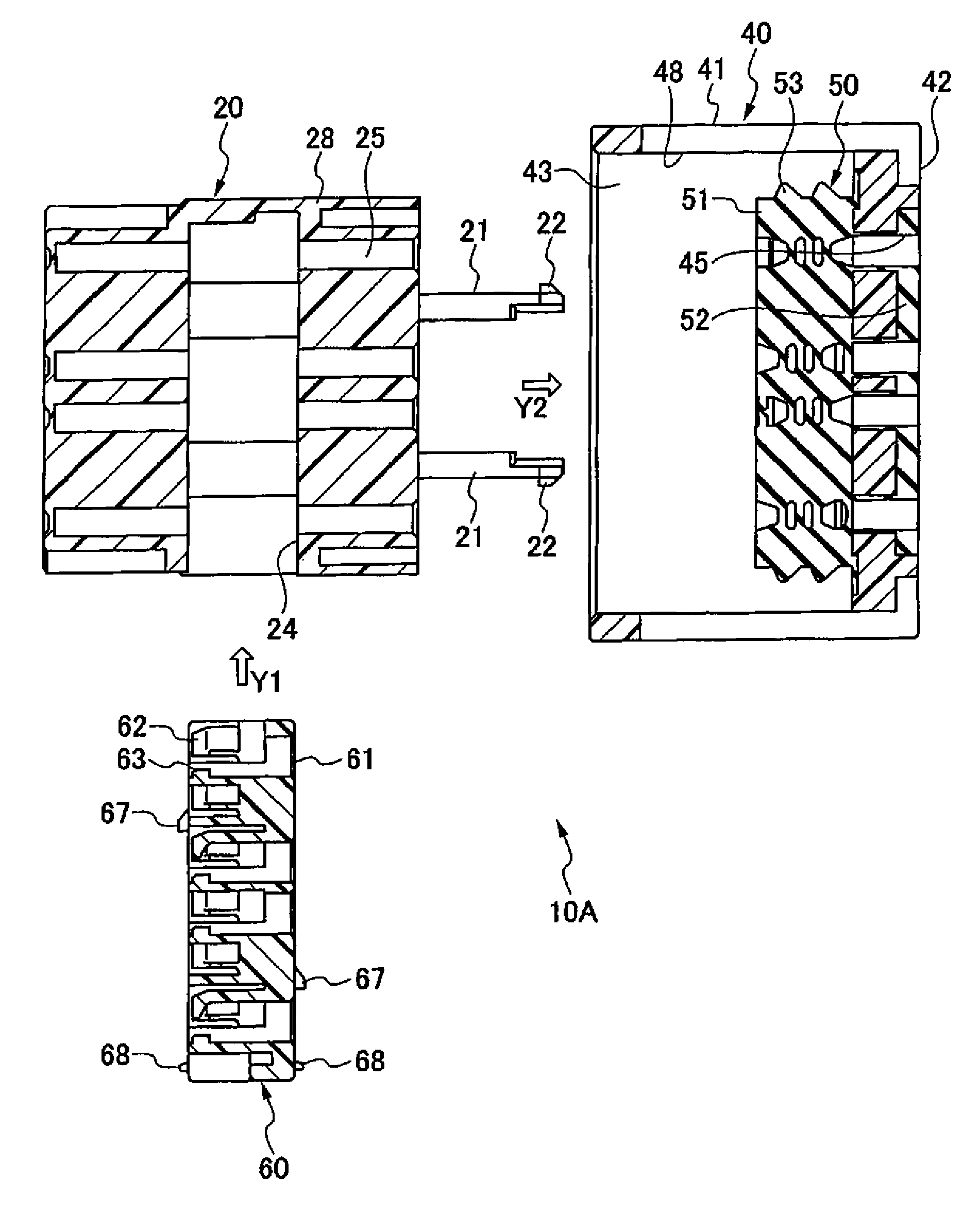
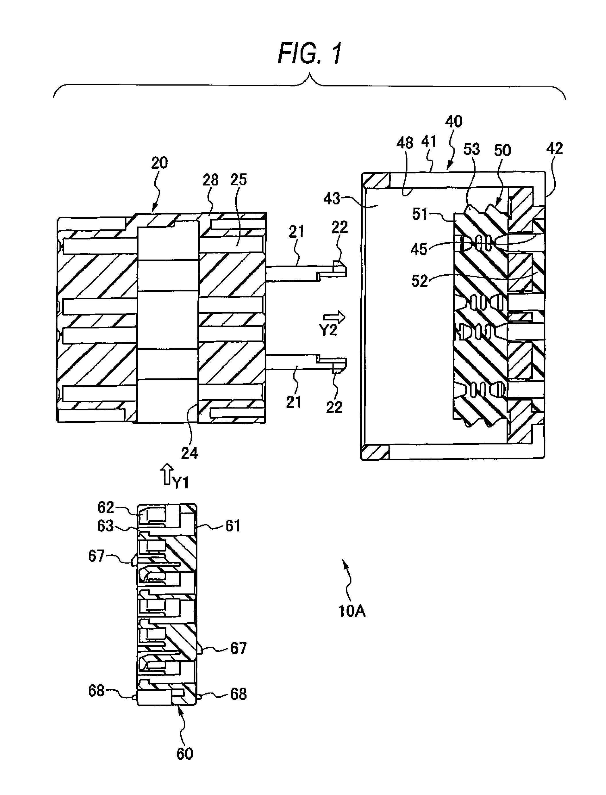
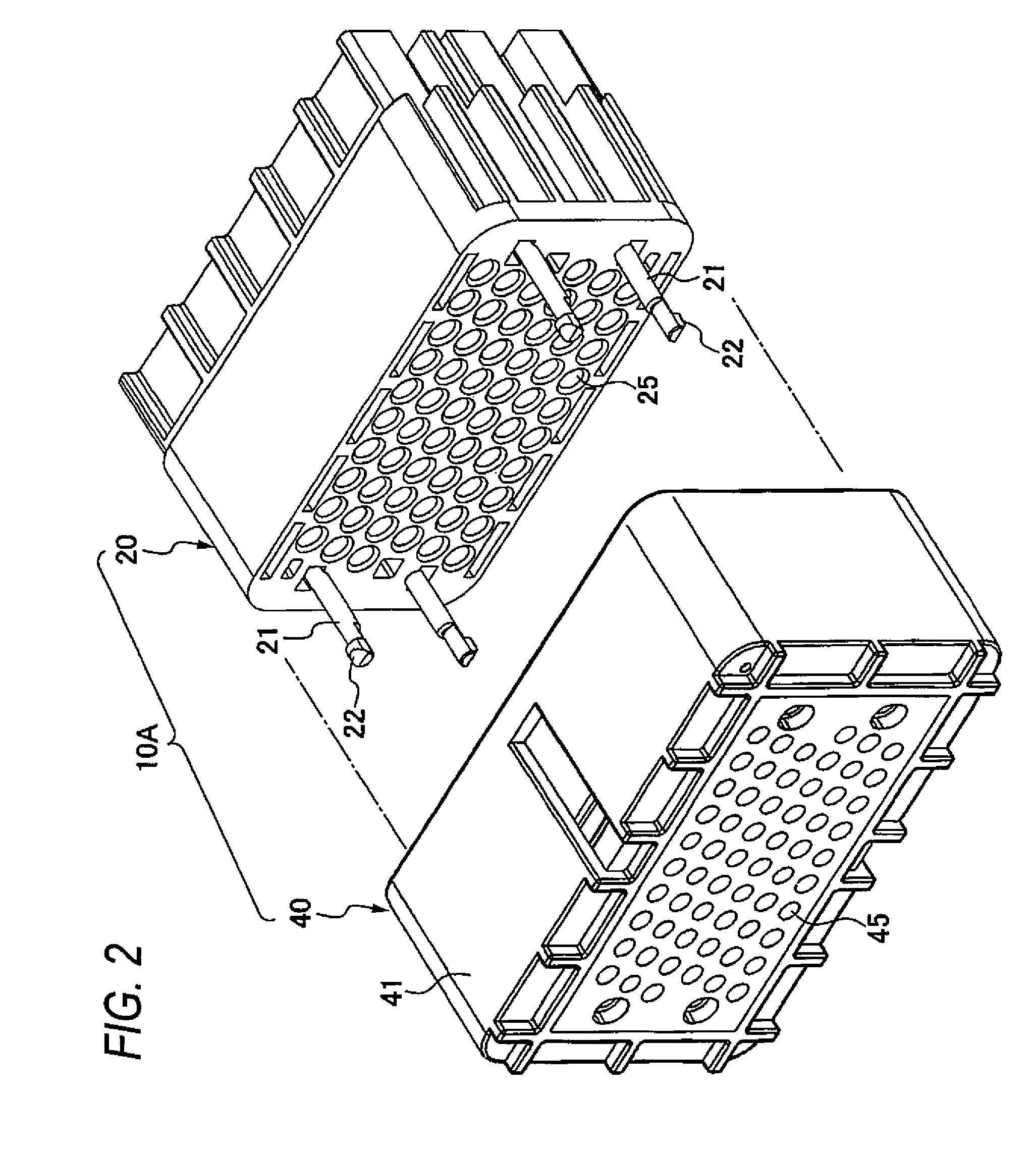
[0049]FIG. 1 is a side sectional view showing a relation between an inner housing 20, an outer housing 40 and a spacer 60 which form a connector housing 10A of a connector of an exemplary embodiment. FIG. 2 is a perspective view showing a relation between the inner housing 20 and the outer housing 40. FIG. 3 is a partly broken perspective view showing the inner housing 20 and the outer housing 40. FIG. 4 is a side sectional view showing a state that the inner housing 20 with which the spacer 60 is temporarily engaged is attached to the outer housing 40. FIG. 5 is partly broken perspective view showing the state illustrated in FIG. 4. FIG. 6 is a front view of the spacer 60. FIG. 7 is a partly enlarged view of FIG. 6. FIG. 8 is a perspective view of the spacer 60 seen from a front surface side. FIG. 9 is a partly enlarged view of FIG. 8. FIG. 10 is a perspective view seen ...


PUM


Abstract

Terminal insert holes 61 are provided in a spacer 60 inserted into an inner housing. In each of the terminal insert holes 61, a lance 62 is provided. The lance is arranged in an obliquely upper position relative to the vertical direction and the transverse direction seen from, a central part of the terminal insert hole 61. A bending direction of each lance is set to a direction substantially corresponding to the oblique direction. Further, in the spacer 60, an engaging protrusion part 63 is provided as a mainly terminal engaging part. Thus, the spacer is pushed in to a mainly engaged position from a temporarily engaged position to shift a temporary engagement by the lance to a main engagement by the engaging protrusion part. In an end part of an engaging edge part 63a of the engaging protrusion part 63, an inclined surface 63c is provided. The inclined surface is allowed to abut on a rotating direction position control part 84 of a terminal 80 to easily rotate the terminal by pushing the spacer.

Description

BACKGROUND OF THE INVENTION[0001]1. Field of the Invention[0002]The present invention relates to a connector that prevents a terminal inserted into a terminal insert hole from a rear part from slipping out by a flexible lance provided so as to face an inner space of the terminal insert hole.[0003]2. Description of the Related Art[0004]Usually, in most of connectors used for a vehicle, square terminal insert holes are ordinarily formed in connector housings as shown in patent literature 1, and square terminals having square electric connecting parts in their front parts are respectively inserted into the terminal insert holes. When the square terminal is used, a directional performance or orientation of the terminal on an axis needs to be recognized during an insertion of the terminal into the terminal insert hole. However, with the progress of a miniaturization of the connector, when the terminal is designed to be miniaturized, as the terminal is smaller, it is the more difficult to...

Claims


Application Information

Patent Timeline
Patent Type & Authority Patents(United States)
IPC IPC(8): H01R13/625
CPCH01R13/4361H01R13/4223
Inventor SAKAMOTO, NOBUYUKI
Owner YAZAKI CORP
Why Eureka
Try Eureka