
Multi-battery pack battery system with direct communication between controller and the battery packs

a battery system and battery pack technology, applied in secondary cell servicing/maintenance, safety/protection circuits, instruments, etc., can solve the problem of disadvantageous generation of time gaps in battery pack operation

Active Publication Date: 2014-12-09
MURATA MFG CO LTD
View PDF8 Cites 3 Cited by
  • Summary
  • Abstract
  • Description
  • Claims
  • Application Information

AI Technical Summary

Benefits of technology

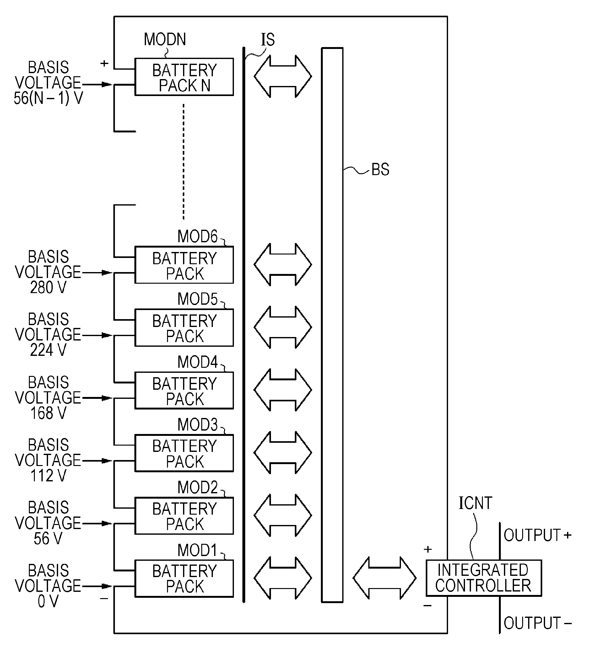
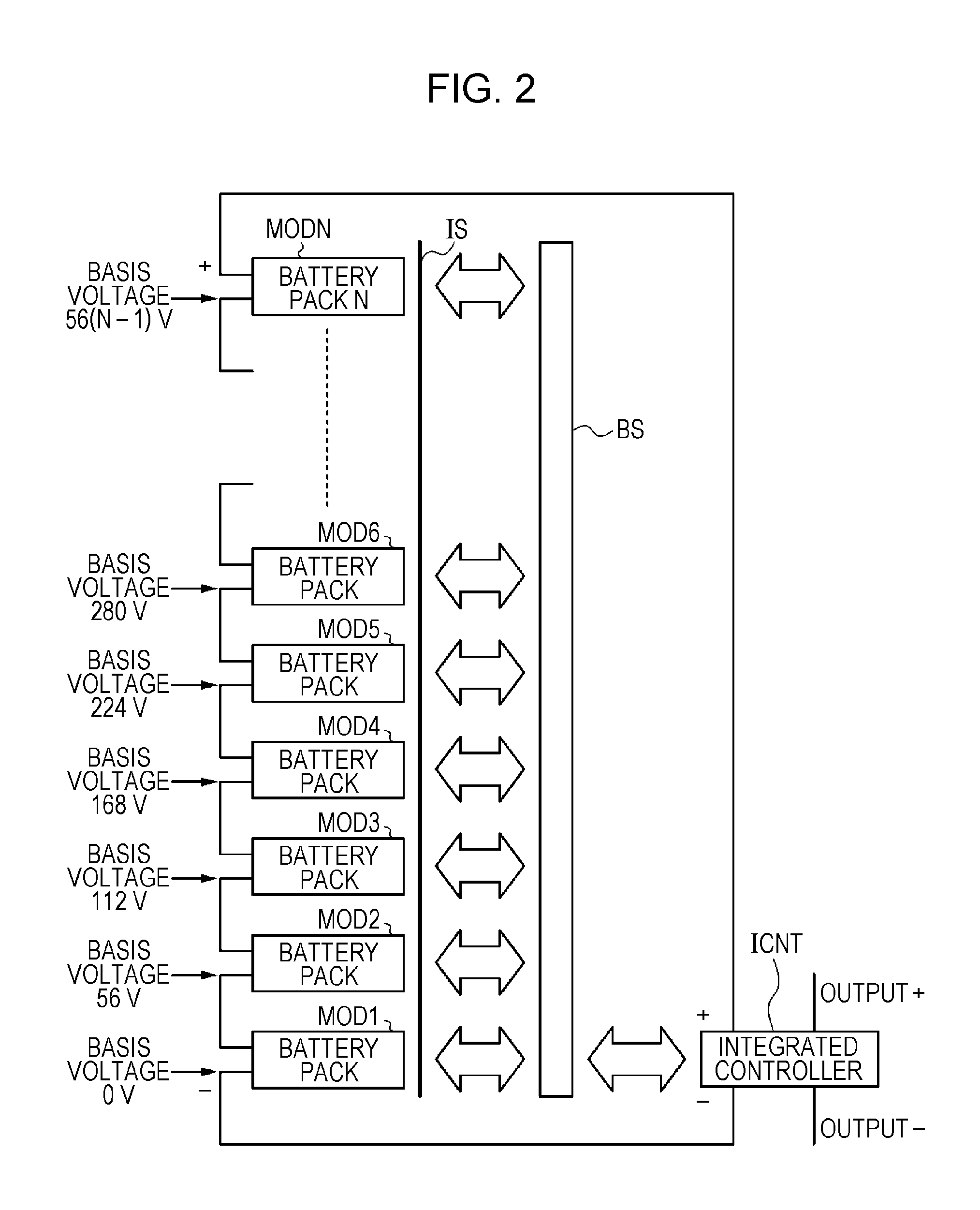
[0037]It is desirable to provide a battery system which is capable of preventing an increase of a breakdown voltage of an insulating interface and in which signal transmission between a controller of each battery pack and an integrated controller is directly performed through no microprocessor.
[0044]According to the embodiment of the present invention, in a case where a signal transmission system among battery packs is configured, it is sufficient for the insulating interfaces to insulate only potential differences among the battery packs. Therefore, even though the number of battery packs which are connected in series is increased, it is sufficient for the insulating interfaces to have a dielectric strength voltage up to a voltage obtained by adding a signal voltage to a voltage of one battery pack at most. In the embodiment of the present invention, a signal is transmitted among the battery packs via no microprocessor, and thus the signal transmission can be directly performed. Accordingly, an occurrence of time lag in the signal transmission between the controllers of the respective battery packs and the integrated controller can be prevented.

Problems solved by technology

As a result, time gaps are disadvantageously generated in operations of the plurality of battery packs which are included in a battery system.

Method used


Image

  • Multi-battery pack battery system with direct communication between controller and the battery packs
  • Multi-battery pack battery system with direct communication between controller and the battery packs
  • Multi-battery pack battery system with direct communication between controller and the battery packs

Examples


Embodiment Construction

[0067]Embodiments of the present invention will be described in the following order.

[0068]Embodiments which will be described below are preferred embodiments of the present invention and various technically-preferable limitations are given. However, it should be noted that the scope of the present invention is not limited to these embodiments unless a description limiting the present invention is given in the following description.

1. Embodiment of the Present Invention

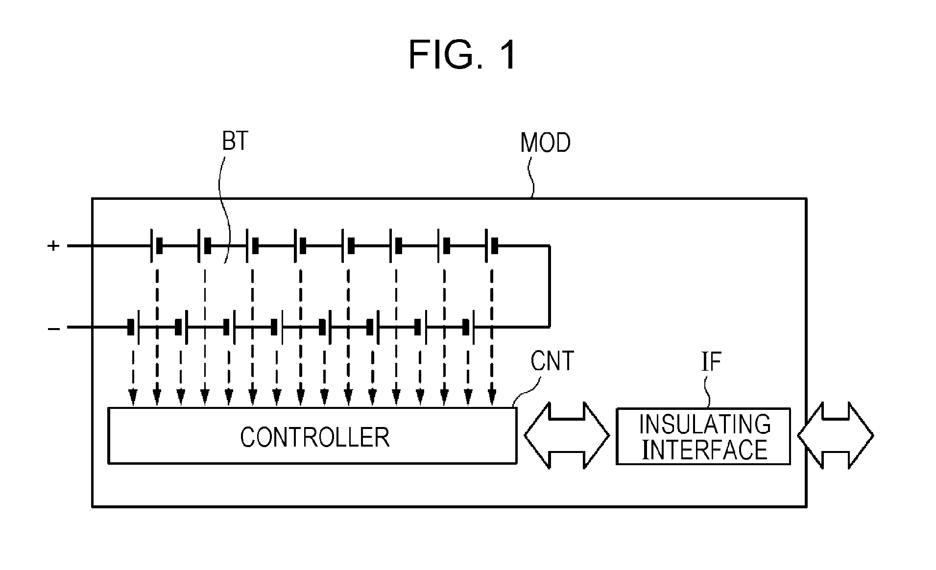
[0069]As shown in FIG. 8, in a battery pack MOD according to an embodiment of the present invention, a controller CNT is provided to a battery unit BT in which a plurality of battery cells, for example, 16 battery cells (for example, lithium-ion batteries) are connected in series. The controller CNT outputs information of inside states such as a voltage, current, and a temperature of each of the cells of the battery unit BT. For example, one battery pack MOD outputs 16×3.5 V=56 V.

[0070]Further, as shown in FIG. 9, N pi...


PUM

PropertyMeasurementUnit
voltageaaaaaaaaaa
basis voltageaaaaaaaaaa

Abstract

A battery system includes a battery pack configured to include at least a plurality of battery cells that are connected in series, a monitor that monitors a state of the plurality of battery cells, and a controller to which an output of the monitor is supplied, a battery pack module in which the battery pack in a first order to the battery pack in an Nth order are connected in series, and an integrated controller that is connected with the battery pack in the first order of the battery pack module. Isolators are respectively disposed among the battery pack in the first order to the battery pack in the Nth order, and a signal is transmitted from the battery pack in an order of n−1 (N≧n≧2) to the battery pack in an order of n via one of the isolators.

Description

BACKGROUND OF THE INVENTION[0001]1. Field of the Invention[0002]The present invention relates to a battery system using a number of battery cells.[0003]2. Description of the Related Art[0004]In a case where a number of battery cells such as hundreds of battery cells are used so as to generate a large output, such configuration that a plurality of battery packs are connected in series is employed. Such configuration is called a battery system. A battery pack is a unit obtained by assembling a plurality of battery cells and a controller. A battery pack MOD is configured as shown in FIG. 1. A controller CNT is provided to a battery unit BT in which a plurality of battery cells, for example, 16 battery cells (for example, lithium-ion batteries) are connected in series. The controller CNT outputs information of inside states such as a voltage, current, and a temperature of each of the cells of the battery unit BT. For example, one battery pack MOD outputs 16×3.5 V=56 V.[0005]Further, as ...

Claims


Application Information

Patent Timeline
Patent Type & Authority Patents(United States)
IPC IPC(8): H01M10/46H01M10/42H02J7/00H02J7/02
CPCH01M10/4207H02J7/0021H02J7/0026Y02E60/12Y02T90/16B60L2240/545B60L2240/547B60L2240/549B60L58/18B60L58/21Y02E60/10Y02T10/70H02J7/0013H02J7/00302H02J7/00306H02J7/0048H02J7/00H01M10/44G01R31/36
Inventor KUMAGAI, EIJISATO, MORIHIKO
Owner MURATA MFG CO LTD
Learn More