A Rigid Body Modal Test Method for Powertrain Mounting System under Loaded Condition

A powertrain and test method technology, applied in vehicle testing, machine/structural component testing, vehicle suspension/shock-absorbing mechanism testing, etc. Space limitations and other issues, to achieve the effect of saving test costs, practical test methods, and saving test time

Active Publication Date: 2012-02-08
HUAWEI TEHCHNOLOGIES CO LTD
View PDF6 Cites 3 Cited by
  • Summary
  • Abstract
  • Description
  • Claims
  • Application Information

AI Technical Summary

Problems solved by technology

While the exciter or hammer provides a point force, excessive force may cause damage to the powertrain
In addition, the arrangement of the exciter or the operating space of the hammer is also strictly limited by the space in the engine compartment
Therefore, the commonly used modal test methods using exciters or hammers are difficult to implement under loading conditions. So far, there is no very effective test method

Method used


Image

  • A Rigid Body Modal Test Method for Powertrain Mounting System under Loaded Condition
  • A Rigid Body Modal Test Method for Powertrain Mounting System under Loaded Condition

Examples


Embodiment 1

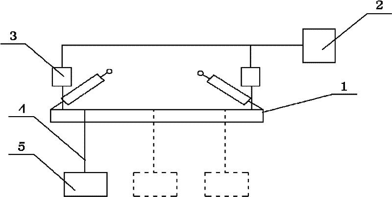
[0025] Example 1: Such as figure 1 As shown, a rigid body modal test method of a powertrain suspension system under loading conditions, the equipment part includes a powertrain suspension device 1, a vibration sensor 3 and a data acquisition device 2 for testing, and also includes A weight 5 and a rope 4 used for auxiliary testing. The weight of the weight 5 is two-fifths of the total weight of the powertrain suspension device 1 of the vehicle under test. Two vibration sensors 3 are arranged on the powertrain suspension device 1, and the aforementioned vibration sensors 3 are connected to the data collection device 2.

[0026] Before the preparation of the rigid body modal test method, the whole vehicle is raised to a certain height by a lift, and then the following test method steps are implemented:

[0027] Step S1: Suspend the weight 5 on the side of the powertrain suspension device 1 via the rope 4;

[0028] Step S2: Reinitialize the modal testing and analysis software on the d...

Embodiment 2

[0032] Embodiment 2: Before the preparation of the rigid body modal test method, the four wheels of the whole vehicle are emptied and placed on an inspection platform with a trench in the middle. The rest is the same as in Example 1.

Embodiment 3

[0033] Embodiment 3: In steps S1 and S4, by adding a sheath to the rope 4 to increase the force surface between the rope 4 and the powertrain suspension device 1 to avoid excessive local force and prevent the powertrain Partially excessive force causes damage. The rest is the same as in Example 2.


PUM


Abstract

The invention discloses a rigid body modal test method of a power assembly suspension system under the vehicle loading condition. The method is to hang a heavy object on the power assembly suspension under the vehicle loading condition, and cut the rope for hanging the heavy object. A sudden release of the force acting on the powertrain suspension device stimulates its free vibration, and immediately triggers the data acquisition device to record and save the data on the vibration sensor at this time. The rigid body mode of the suspension system measured by this method, as well as the natural frequency and decoupling rate of each order obtained from it, are the actual and true natural frequency and decoupling rate of the vehicle under test, so it is the most direct method for its performance. , the truest and most reliable test. Moreover, this test method can be carried out on any complete vehicle, and it only needs to provide an appropriate amount of weight, and does not need to design and process the test bench, so basically no test cost is required. Obviously, the test time and test cost can be greatly saved.

Description

Technical field [0001] The invention relates to the field of vehicle loading performance testing, and more specifically to a rigid body modal testing method of a powertrain suspension system under vehicle loading conditions. Background technique [0002] The main function of the powertrain suspension system is to achieve two-way vibration isolation between the powertrain and the body. The vibration isolation performance mainly depends on the vibration decoupling design and frequency shift design of the suspension system (that is, the reasonable configuration of natural frequencies). [0003] At present, the two are usually designed and verified through theoretical and simulation calculations. The actual performance achieved under actual loading conditions and the calculated results are affected by approximation errors, manufacturing errors of suspension components, installation errors and other factors. There are often considerable differences. [0004] Through the rigid body modal...

Claims


Application Information

Patent Timeline
Patent Type & Authority Patents(China)
IPC IPC(8): G01M17/04G01M7/02G01M17/007
Inventor 单树军孔令彬王海林刘强马芳武李书福杨健赵福全
Owner HUAWEI TEHCHNOLOGIES CO LTD
Why Eureka
Try Eureka