Rear camera backup assistance with touchscreen display using two points of interest

a touchscreen display and touchscreen technology, applied in the field of rearview camera systems, can solve problems such as difficulty in steering the vehicle of some peopl

Inactive Publication Date: 2012-03-20
FORD GLOBAL TECH LLC
View PDF3 Cites 47 Cited by
  • Summary
  • Abstract
  • Description
  • Claims
  • Application Information

AI Technical Summary

Benefits of technology

[0005]The present invention provides assistance for backup maneuvers beyond just showing the hitch and trailer on the rear image. Guidance icons are provided on the rearview display based on simple user inputs without requiring additional external sensors.

Problems solved by technology

However, since the actual backup path has to be controlled by the driver in a way that feels unnatural for most drivers, it remains difficult for some to steer the vehicle so that the trailer hitch moves in the desired manner on the backup display.

Method used


Image

  • Rear camera backup assistance with touchscreen display using two points of interest
  • Rear camera backup assistance with touchscreen display using two points of interest
  • Rear camera backup assistance with touchscreen display using two points of interest

Examples


Embodiment Construction

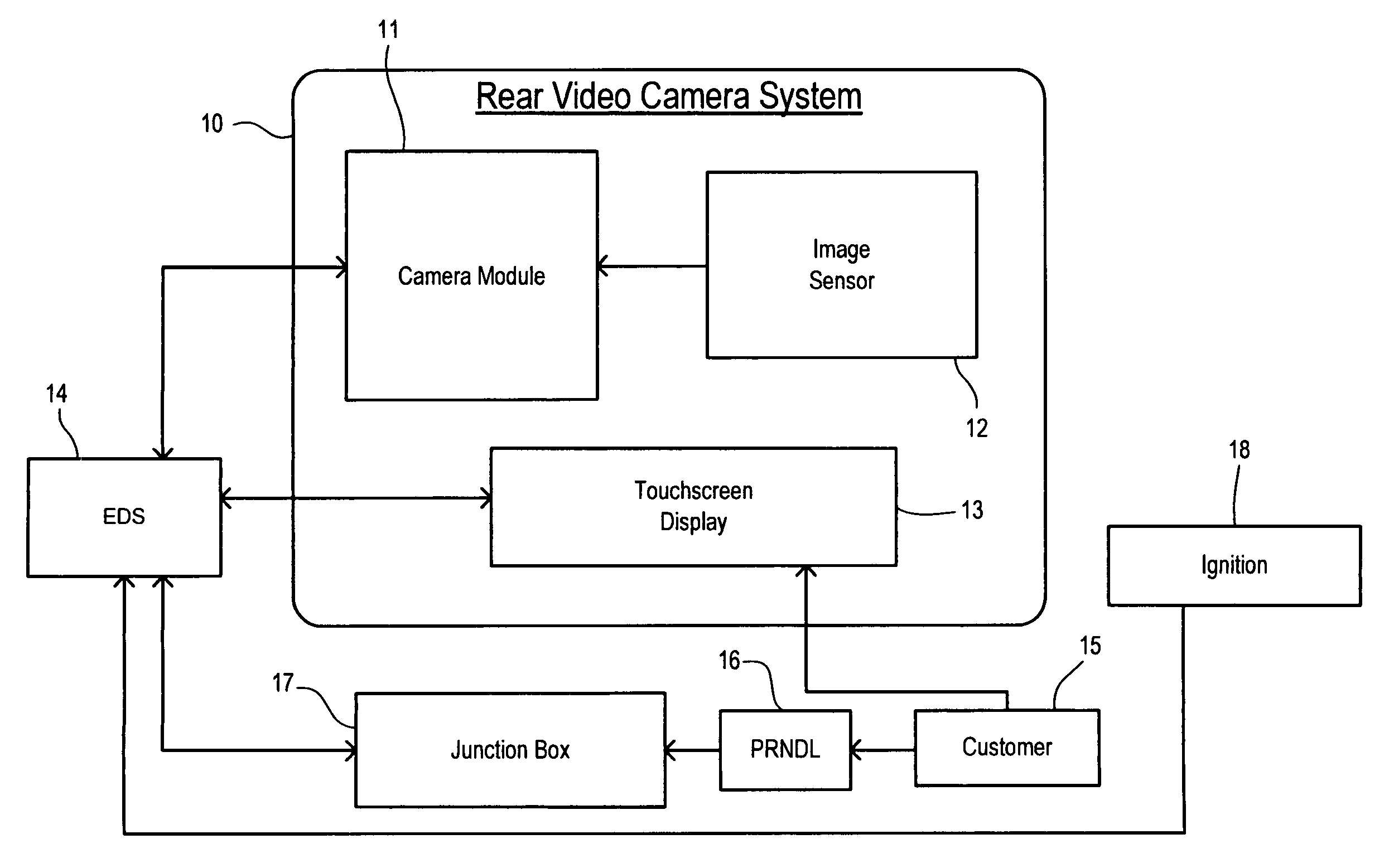
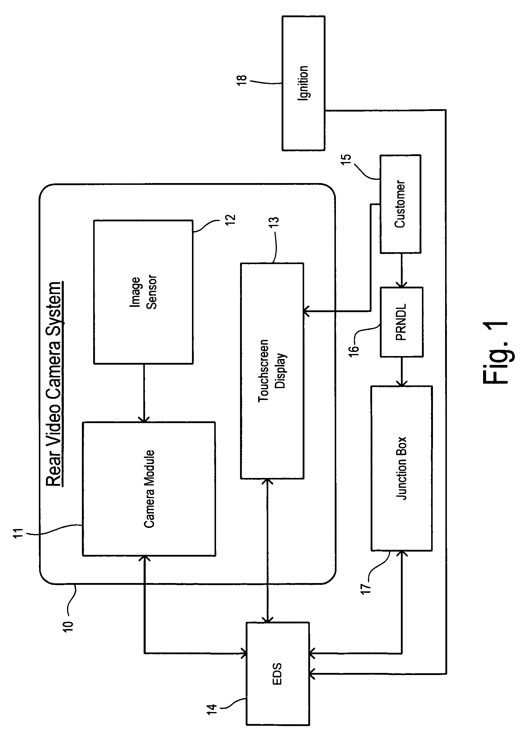
[0010]Referring to FIG. 1, backup assist apparatus is shown for installation in a motor vehicle. A rear video camera system 10 includes a camera module 11, image sensor 12, and touchscreen display 13. Image sensor 12 is deployed on the vehicle with a view to the rear of a vehicle (not shown) and may be comprised of a CCD or CMOS imager providing a conventional video signal to camera module 11. Camera module 11 may be coupled to touchscreen display 13 via an electrical distribution system (EDS) 14 such as a wiring harness. Alternatively, camera module 11 and touchscreen display 13 can be directly connected or integrated into a single unit. Image sensor 12 is shown with a direct connection to camera module 11. Image sensor 12 can be included as part of module 11 in one box or may be separate from module 11 and can be connected via EDS 14. Using the image data provided by image sensor 12, camera module 11 generates various camera views together with overlays as described below that are...


PUM


Abstract

Assistance for a backup maneuver of a motor vehicle in which a first point of interest on the vehicle is moved toward a second point of interest remote from the vehicle. A rear contextual view is displayed on an electronic display obtained from a rearward directed image sensor on the vehicle. A zoom window is manually placed on the electronic display to include the second point of interest. The zoom window is enlarged, and the location of the second point of interest is manually identified within the enlarged zoom window. The identified location of the second point of interest is transformed into target positional coordinates. The rear contextual view redisplayed with a target icon at the target positional coordinates. The location of the first point of interest is manually identified on the rear contextual view and transformed into starting positional coordinates. A start icon is displayed at the starting positional coordinates in the rear contextual view. A target line is determined between the target positional coordinates and the starting positional coordinates. A path line icon is displayed in the rear contextual view corresponding to the determined target line. A bearing line is displayed in the rear contextual view extending from the start icon. The target positional coordinates are re-determined as the rear contextual view shifts during the backup maneuver. The target icon and the path line icon are updated in response to the re-determined target positional coordinates.

Description

CROSS REFERENCE TO RELATED APPLICATIONS[0001]Not Applicable.STATEMENT REGARDING FEDERALLY SPONSORED RESEARCH[0002]Not Applicable.BACKGROUND OF THE INVENTION[0003]The present invention relates in general to vehicular rearview camera systems, and, more specifically, to displaying backup maneuver steering directions on an electronic display.[0004]Rear vision systems have become available for use on motor vehicles to monitor the area behind the vehicle by providing a camera image on a display panel visible to the driver. Such systems increase visibility for the driver of any obstacles that may be present while backing up. Some rear vision systems have been specifically intended to assist in the connecting of a trailer hitch to a trailer. By allowing the driver to see the trailer hitch and the trailer together in the field of view of a rear camera, the driver is better able to back up the vehicle so that the trailer hitch is accurately placed at the hitch-receiver on the trailer. However...

Claims


Application Information

Patent Timeline
Patent Type & Authority Patents(United States)
IPC IPC(8): G08B21/00
CPCB60K35/00G06F3/0481H04N5/232B62D15/0295B60K2350/1028B60K2350/1088G06F2203/04806B60D1/36B60K2370/1438B60K2370/173
Inventor GHNEIM, MAHER M.
Owner FORD GLOBAL TECH LLC
Why Eureka
Try Eureka