
Method of sheathing a stent

a technology of stent and sheath, which is applied in the field of medical devices or devices, can solve the problems of time-consuming and expensive procedure for hand placement and removal of the sheath, and significant limitations of technology,

Active Publication Date: 2012-03-27
MACHINE SOLUTIONS
View PDF14 Cites 10 Cited by
  • Summary
  • Abstract
  • Description
  • Claims
  • Application Information

AI Technical Summary

Benefits of technology

[0011]The invention provides a method of sheathing a stent, particularly during a crimping process, and an apparatus for sheathing a stent, in particular during a crimping process, which are practical, reliable, accurate and efficient, and which are believed to fulfill the need and to constitute an improvement over the background technology.

Problems solved by technology

At present, there are a number of problems in crimping coated stents which occur because the coating is typically soft and somewhat fragile.
This technology is believed to have significant limitations and shortcomings.
Hand placement and removal of the sheath is a time consuming and expensive procedure.
Also, tubular sheaths are typically expensive and difficult to apply.

Method used


Image

  • Method of sheathing a stent
  • Method of sheathing a stent
  • Method of sheathing a stent

Examples


Embodiment Construction

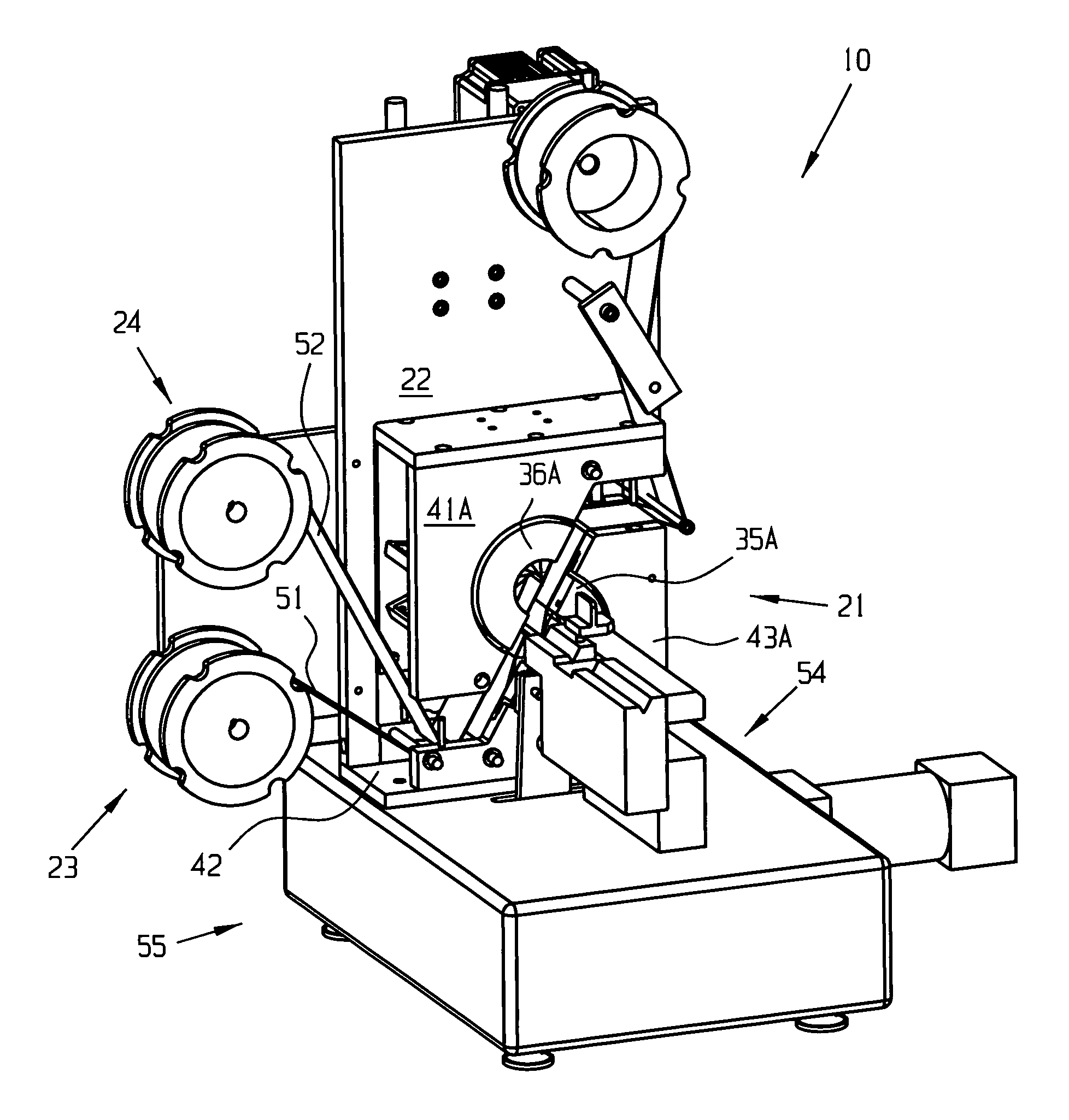
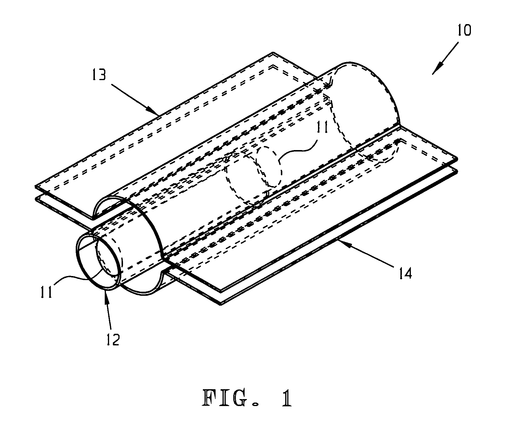
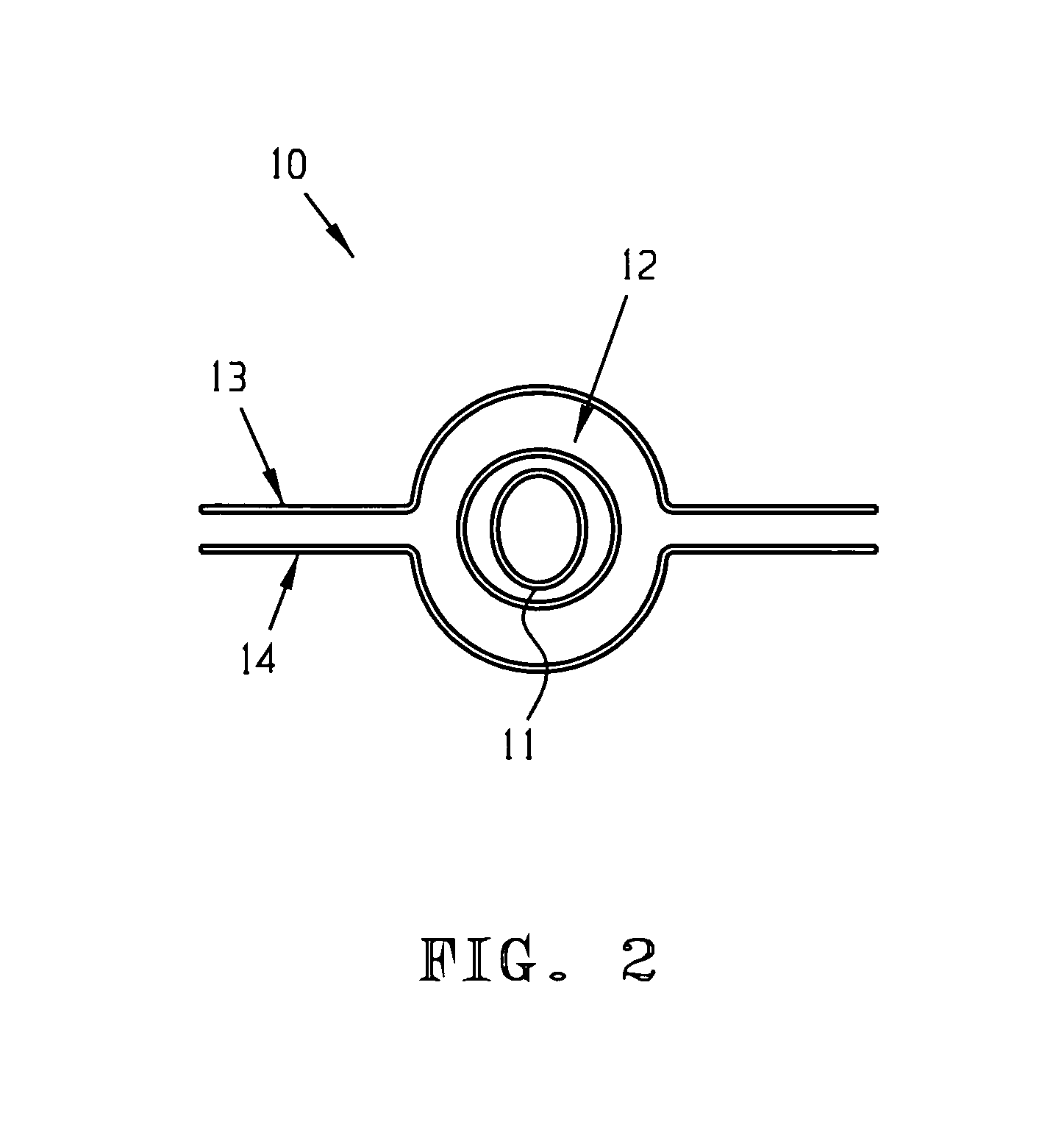
[0039]The sheathing process and apparatus of the present invention utilize a pair of flat films of material. No tubular sheath is required as in the prior art. Referring to FIGS. 1 and 2, a sheathed stent assembly 10, comprises a catheter body 11 and a stent 12, with a first or upper 13 and a second or lower 14 flat film, ribbon, or half sheath. The films 13 and 14 are disposed on each side of the stent 12, for example a drug coated stent, also commonly called a drug eluting stent (DES). The films 13 and 14 are preferably automatically fed into one side of a crimp head (See later Figures) in continuous paths. The paths pass through and out the crimp head. The sheaths 13 and 14 protect the stent 12 during a crimping process. The continuous paths eliminate the need to manually handle the stent / catheter assembly 10 in order to place a sheath. Film material, preferably flat, and in a continuous or endless roll or web is lower cost than individual tubular sheaths. Film material is also a...


PUM

PropertyMeasurementUnit
forceaaaaaaaaaa
softaaaaaaaaaa
timeaaaaaaaaaa

Abstract

A method of sheathing a stent including the steps of providing a stent assembly including a catheter member and a stent member disposed about the catheter member; placing a first sheath film adjacent one side of the stent assembly; placing a second sheath film adjacent an opposite side of the stent assembly, and compressing the stent assembly, whereby the first and second sheath films move toward each other and substantially surround the stent assembly. The first and second sheath films are provided in rolls. Compressing is implemented by a radial compression mechanism. The first and second sheath films pass through the radial compression mechanism. Compressing sheaths the stent assembly and crimps the stent onto the catheter. As an alternative to two sheath films, a single film may be used, whereby compressing surrounds the stent assembly with the single sheath film. Also disclosed in an apparatus for sheathing a stent, including a compressing mechanism; a sheath film supply; a film feeder for moving at least one sheath film from the film supply through the compressing mechanism, and a stent input system for moving a stent assembly into the crimping mechanism.

Description

CROSS-REFERENCE TO RELATED APPLICATIONS, IF ANY[0001]This application claims the benefit under 35 U.S.C. §119(e) of U.S. Provisional Patent Application Ser. No. 60 / 624,432, filed Nov. 2, 2004, which is hereby incorporated by reference.37 C.F.R. §1.71(e) AUTHORIZATION[0002]A portion of the disclosure of this patent document contains material which is subject to copyright protection. The copyright owner has no objection to the facsimile reproduction by anyone of the patent document or the patent disclosure, as it appears in the US Patent and Trademark Office patent file or records, but otherwise reserves all copyright rights whatsoever.STATEMENT REGARDING FEDERALLY SPONSORED RESEARCH OR DEVELOPMENT[0003]Not applicable.REFERENCE TO A MICROFICHE APPENDIX, IF ANY[0004]Not applicable.BACKGROUND OF THE INVENTION[0005]1. Field of the Invention[0006]The present invention relates, generally, to medical apparatus or devices, processes for making such apparatus, and apparatus for making such ap...

Claims


Application Information

Patent Timeline
Patent Type & Authority Patents(United States)
IPC IPC(8): B21D39/00B21D41/00B21D39/04A61F2/82
CPCA61F2/95B29C63/065A61F2/82A61F2002/30067A61F2002/9522Y10T29/49913Y10T29/53126Y10T29/53065Y10T29/53987Y10T29/53996B29L2031/7534A61F2/9522
Inventor SEYLER, PAUL R.MOTSENBOCKER, THOMASBATTAGLIA, JAMES L.
Owner MACHINE SOLUTIONS
Learn More