
Shoe with sensors, controller and active-response elements and method for use thereof

a technology of active response and golf shoes, applied in the field of golf shoes, can solve the problems of unsatisfactory solution, unsatisfactory solution, and significant effort of the golfer, and achieve the effect of less movemen

Active Publication Date: 2012-03-27
ACUSHNET CO
View PDF26 Cites 39 Cited by
  • Summary
  • Abstract
  • Description
  • Claims
  • Application Information

AI Technical Summary

Benefits of technology

The present invention provides golf shoes that can distinguish between walking and swinging a golf club. The shoes have a first set of characteristics when the person is walking and a second set of characteristics when they are swinging. The second set of characteristics is indicative of a stable shoe, which means the shoe is more stable and less flexible when the person is swinging the club. The shoes have a controller that determines if the person is walking or swinging and sends an output current to the shoes to change from the first set of characteristics to the second set of characteristics. This allows for a more stable and flexible shoe for swinging the club.

Problems solved by technology

This solution is undesirable since it would require too much time and effort on the golfer's part.
This solution is also undesirable because it would also require significant effort from the golfer.
This is not ideal, as it requires the golfer to perform an additional “clicking” action not normally performed when playing golf.
An additional abnormal action may interfere with the golfer's performance.
This action may also subject the golfer to ridicule.
This footwear does not address the game of golf and the functional requirements of a golf shoe.
Moreover, USGA rules prohibit using shoes with stored energy.

Method used


Image

  • Shoe with sensors, controller and active-response elements and method for use thereof
  • Shoe with sensors, controller and active-response elements and method for use thereof
  • Shoe with sensors, controller and active-response elements and method for use thereof

Examples


Embodiment Construction

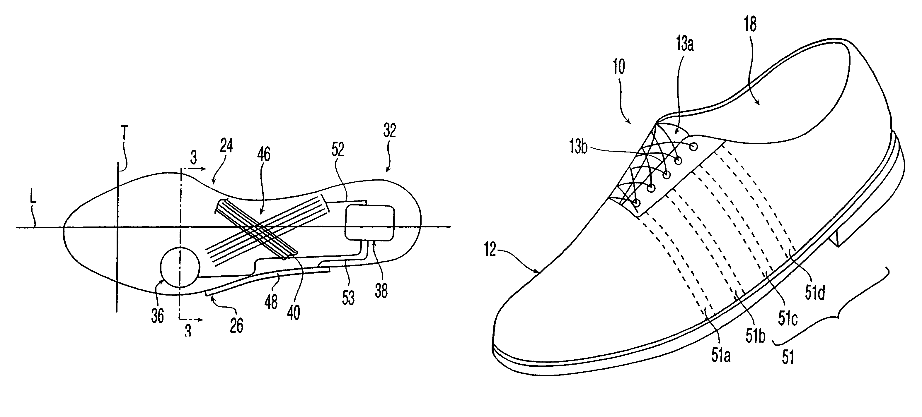
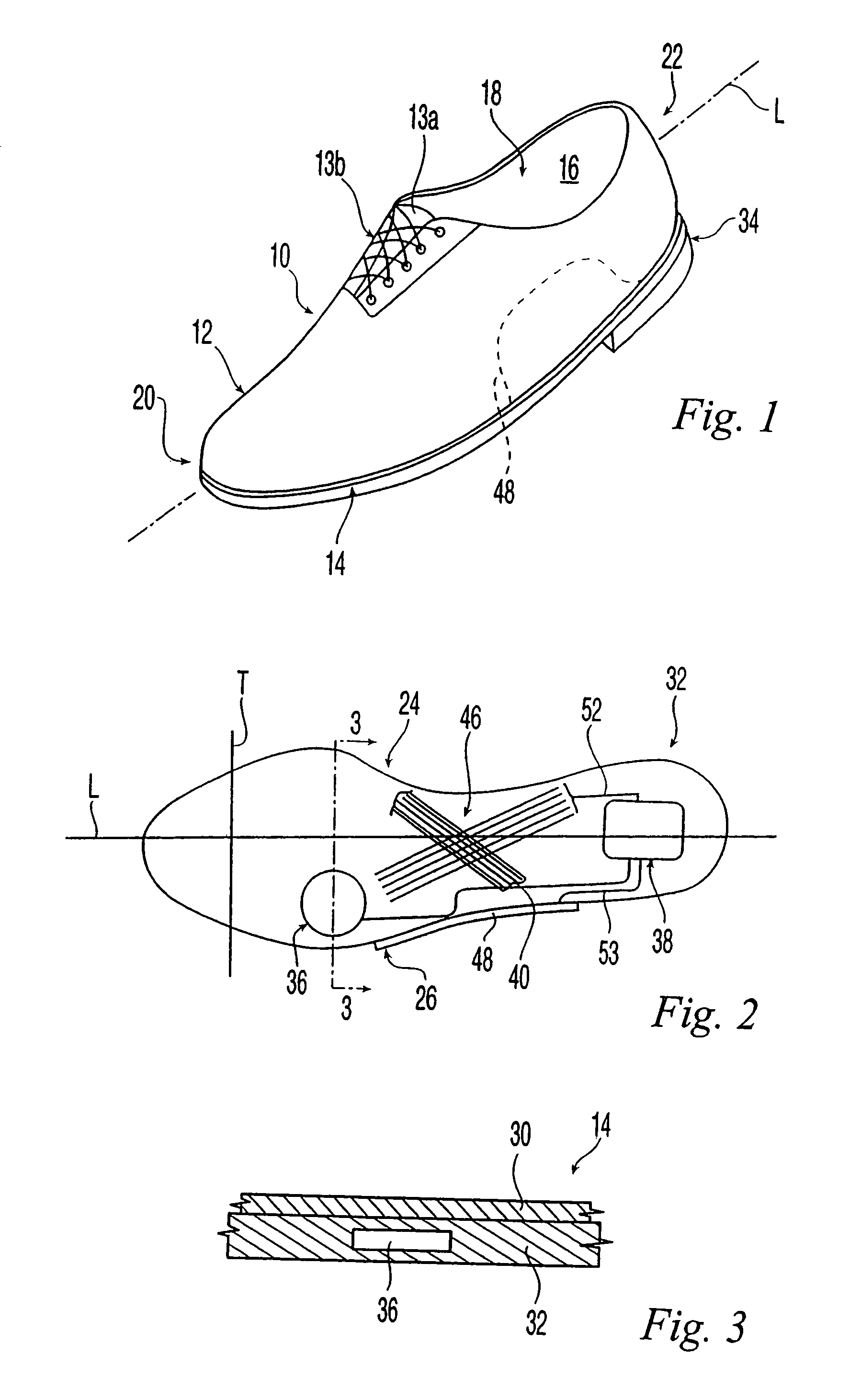
[0032]Referring to FIG. 1, there is illustrated an embodiment of a golf shoe 10 in accordance to the present invention. Either or both right or left shoes could utilize the features of the present invention. The shoe 10 includes an upper 12 and a sole assembly 14. The upper is joined to the sole assembly 14 using cement, stitching or other conventional materials and conventional techniques. Once joined, the upper 12 defines a chamber 16 for receiving a wearer's foot (not shown). The chamber 16 is accessible by an opening 18 in the upper 12.

[0033]For reference purposes, golf shoe 10 includes a front or toe end 20, a rear or heel end 22, and a longitudinal axis L extending between the front end 20 and the rear end 22. Referring to FIGS. 1 and 2, the golf shoe 10 further includes a medial side 24 and a lateral side 26. A transverse axis T perpendicular to the longitudinal axis L extends between the medial side 24 and lateral side 26. When golfers walk, their feet typically move along t...


PUM


Abstract

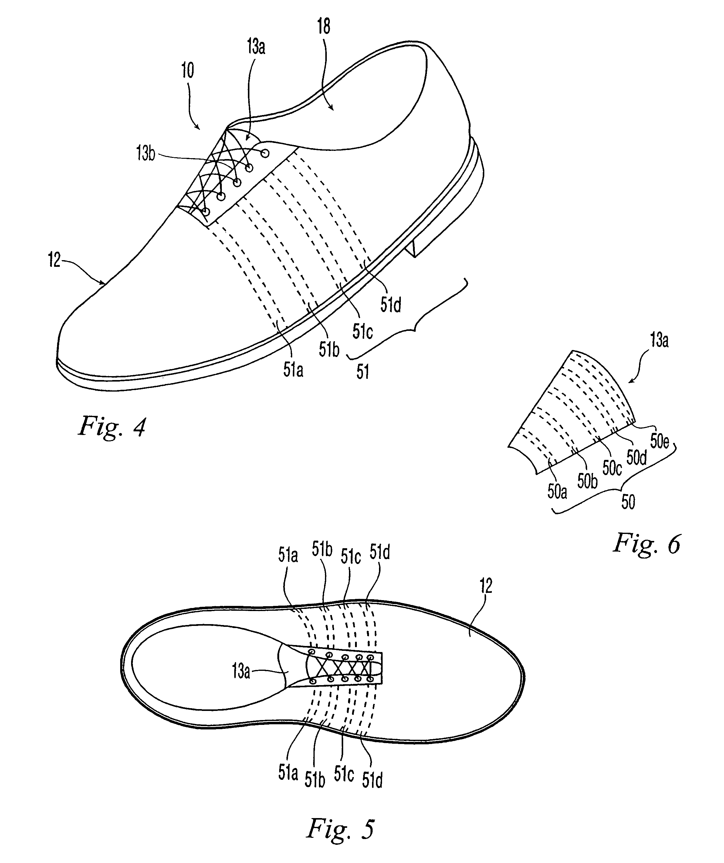
Active-response golf shoes are disclosed. The golf shoes include a plurality of sensors, a controller, and at least one active-response element. The sensor and controller operate to rapidly determine if a golfer is walking or swinging a golf club. Once this determination is made the controller and active-response element rapidly change the shoe's characteristics. If the controller determines that the golfer is walking, the shoe provides a soft and flexible walking platform. If the controller determines that the golfer is swinging, the shoe morphs or changes automatically to provide a stable hitting platform. The controller senses various predetermined conditions such as pressure of the user's foot to determine whether the golfer is walking or swinging. The active-response element is a lateral adjuster having an upper bracket located in the laces area and a lower bracket affixed to the side of the sole, brackets supporting a plurality of electrostrictive polymer bands.

Description

CROSS REFERENCE TO RELATED APPLICATION[0001]This application is a continuation-in-part of U.S. application Ser. No. 11 / 938,808, filed on Nov. 13, 2007 now U.S. Pat. No. 7,552,549, which is a divisional of U.S. application Ser. No. 10 / 790,164, filed on Mar. 1, 2004, now U.S. Pat. No. 7,310,895, both of which are incorporated by reference herein in their entirety.FIELD OF THE INVENTION[0002]The present invention relates to shoes, and more particularly, to golf shoes having sensors, controller, and active-response elements. In addition, the present invention relates to a method for actuating the active-response elements and changing the shoe's characteristics depending on whether the player is walking or swinging his club.BACKGROUND OF THE INVENTION[0003]The game of golf includes long stretches of walking and short moments of swinging a golf club to hit a golf ball. Consequently, golf shoes must perform in two different types of movement that have conflicting design requirements. Golf ...

Claims


Application Information

Patent Timeline
Patent Type & Authority Patents(United States)
IPC IPC(8): A43B5/00
CPCA43B3/0005A43B23/0275A43B13/14A43C1/00A61B5/6807A63B69/0059A63B69/3608A63B69/3667A43B23/0235A43B5/001A61B5/1036A61B2560/0214A63B2069/367A63B2220/56A63B2220/833A63B2220/836A63B2243/0029A43B11/00A63B2102/32A43B3/34
Inventor ROBINSON, DOUGLAS K.ERICKSON, JOHN J.TAYLOR, GORDON B.BEARD, STEVEN E.WEBER, DEREK S.MOISAN, JARED
Owner ACUSHNET CO
Learn More