Expansion joint for modular flooring system

a technology for expanding joints and flooring, applied in single-unit pavings, walls, ways, etc., can solve the problems of significant displacement of the floor from its preplanned location, significant problems with respect to floor maintenance, and the safety of users, and achieve the effect of maintaining the compressive strength of the floor tile system and increasing the frictional characteristics of the top surfa

Active Publication Date: 2012-03-27
SIGNATURE SYST GRP LLC
View PDF25 Cites 19 Cited by
  • Summary
  • Abstract
  • Description
  • Claims
  • Application Information

AI Technical Summary

Benefits of technology

[0009]A modular floor expansion joint is disclosed which provides both a means for absorbing the expansion of adjoining floor tiles and permitting the various expanding or contracting sections of the modular floor to remain flat on the substrate, as well as to permit a minimal amount of misalignment in the application of the floor tiles to a substrate by providing an adjustment means for subsections of the floor. In practice, this permits the insertion of the expansion joint tiles at locations where a misalignment has occurred and been discovered. Once a significant portion of the modular floor has been laid, the adjustability of the modular floor tile expansion joint permits the realignment of neighboring sections of adjoined modular floor tiles to the preplanned topographic location. The expansion joint also prevents the floor to be laid in discontinuous sections which may be moderately misaligned and joined by the adjustable expansion tile.
[0012]In order to maintain the compressive strength of the floor tile system, a series of support webs, or other reinforcing means may be applied to the expansion joint, such that it matches the adjoining floor tiles in height and other critical dimensions, as well as its ability to support the intended load. Lastly, for both cosmetic and functional reasons, the exterior surface of the floor tile may be provided with both decorative embellishments, as well as various ventilation or other functional surface features to permit or prevent the passage of moisture facilitating the passage of persons and vehicles thereover. This is utilized to increase the frictional characteristics of the top surface so that a slippery condition is not provided on the top surface when mounted within the modular flooring system.

Problems solved by technology

While the dimensional changes in each individual tile are relatively small, over a large area with hundreds, perhaps thousands, of interlocked tiles, the cumulative expansion or contraction of the entire flooring system causes significant problems with respect to maintenance of the floor, as well as the safety of the users.
In practice, this expansion of the modular flooring system causes buckling, shifting and cracking of the floor tiles, as well as providing a tripping hazard for persons walking on the floor and potentially causing dangerous conditions which could cause vehicles to be diverted from their intended course over the surface of the modular floor.
Other limitations of the modular flooring system include the requirement that the floor be laid sequentially in order to ensure the appropriate alignment and interlocking of the modular tiles.
In practice, this means that a tile floor must be laid from one location and expanding outwardly from that location on an interlocking basis and cannot be laid in discontinuance sections.
Furthermore, the alignment and location of each tile is very important because small deviations from the preplanned alignment of the tiles over the course of longer distances will result in a floor being significantly displaced from its preplanned location.
This results in significant delays and costs associated with picking up and relaying the various floor tiles once the misalignment has been discovery after a significant number of tiles have been laid.

Method used


Image

  • Expansion joint for modular flooring system
  • Expansion joint for modular flooring system
  • Expansion joint for modular flooring system

Examples


Embodiment Construction

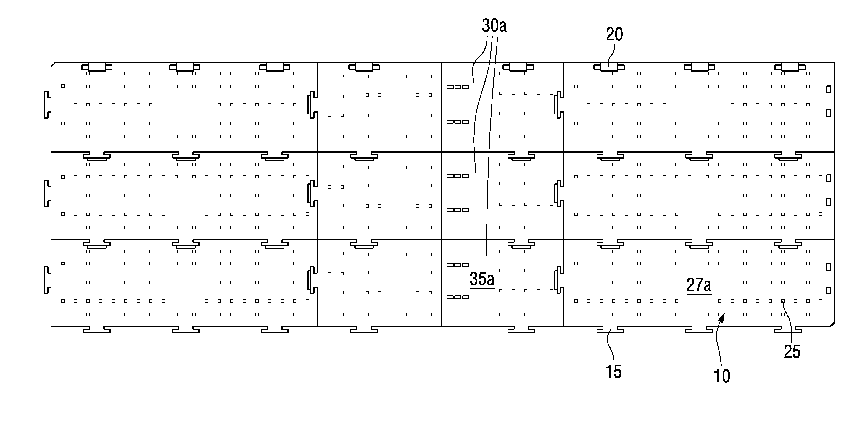
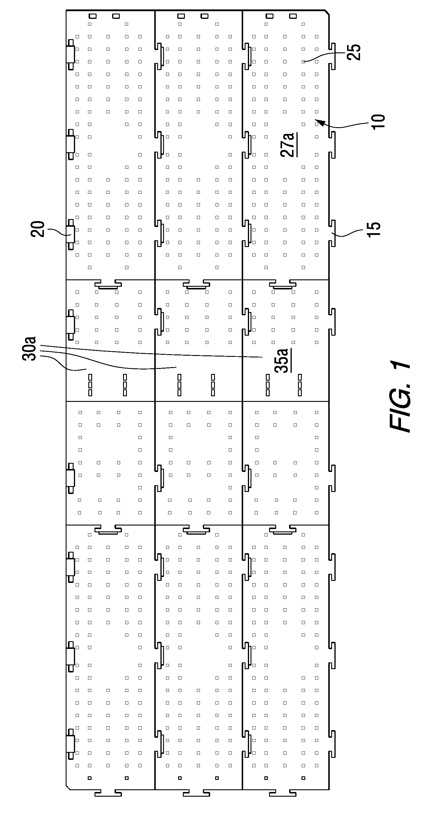
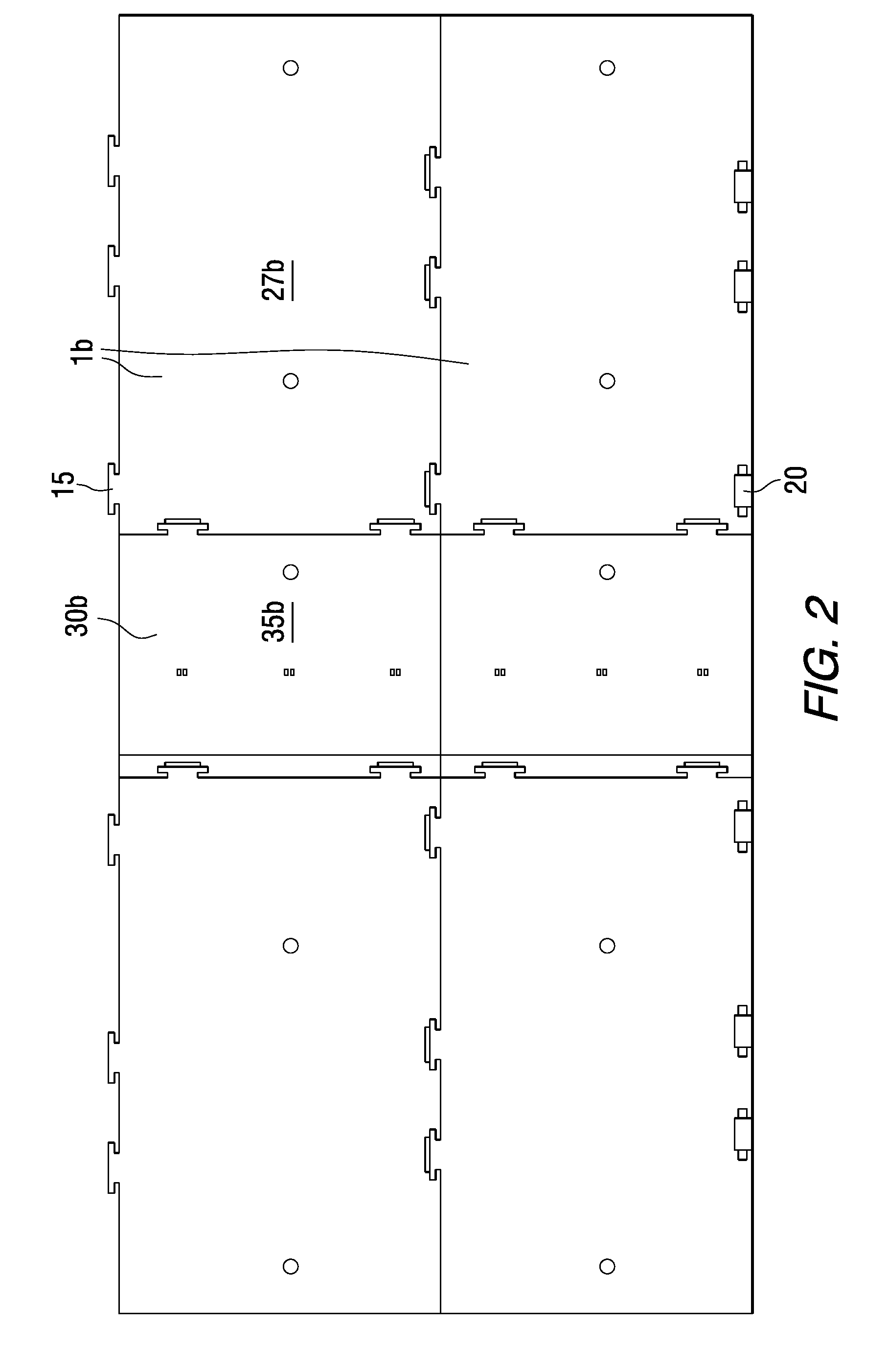
[0022]Referring to FIG. 1, a matrix of modular floor tiles is illustrated having a number of component parts. A first embodiment is depicted in FIG. 1 while a second embodiment is depicted in FIG. 2. Referring now to FIGS. 1 and 2, modular floor tiles of the prior art are identified as floor tiles 1. The first embodiment being identified as embodiment 1a and the second embodiment being 1b. References herein to elements common to both embodiments will identify those same elements by reference numeral where the embodiments differ. The further identifiers, a and b will be used respectively, modular floor tiles 1 are provided in an interlocking matrix 10 which extends in two dimensions in accordance with a preset topographic plan. As discussed previously, the topographic plan is typically directed towards the conveyance or support of equipment, vehicles, personnel and the like and is adapted to conform to the topographic or geographic features of the substrate surface, such as grass, di...


PUM

PropertyMeasurementUnit
transmissionaaaaaaaaaa
strengthaaaaaaaaaa
weightaaaaaaaaaa

Abstract

An expansion joint for a modular flooring system in disclosed, which includes the slidable engagement of two subsections of the expansion joint. The expansion joint is sized such that it is equivalent in overall dimension to the intended adjacent modular floor tiles of which it will form a part within a matrix of such interlocked modular floor tiles. The expansion joint is provided with at least one slot on one module, corresponding to at least one locking pin on the other module. The slot receives and restrains the locking pin and permits the slidable engagement along the longitudinal axes thereof.

Description

BACKGROUND OF THE INVENTION[0001]1. Field of the Invention[0002]The invention relates to an expansion joint for modular flooring. More particularly, the invention relates to the use of a slidable member which is interspersed between tiles of plastic modular flooring, which is adapted to permit relative movement of subsections of the modular flooring during installation.[0003]2. Description of the Prior Art[0004]Modular flooring of various designs has been utilized for a significant period of time to provide a temporary walking or other rigid surface in areas where permanent flooring is either not necessary or prohibitively expensive. More particularly, modular flooring is primarily utilized in commercial settings where a floor is temporarily needed, such as on a grass or artificial turf surface as well as in industrial or construction areas. With respect to industrial or construction areas, temporary flooring may be utilized to provide walkways, driveways, parking areas or other rig...

Claims


Application Information

Patent Timeline
Patent Type & Authority Patents(United States)
IPC IPC(8): E04B2/08
CPCE04F15/10E04F2201/041E04F15/105E01C5/20E01C9/086
Inventor ROSAN, ARNON
Owner SIGNATURE SYST GRP LLC
Why Eureka
Try Eureka