
Side lock apparatus

a side lock and apparatus technology, applied in the direction of mechanical control devices, keyhole guards, instruments, etc., can solve the problems of affecting the quality of the assemblage, the difficulty of synchronizing the positions of the rack pair, and the increase in the number of manhours required for the assemblage, etc., to achieve the effect of reducing the mounting space, good operability and high-quality feel

Inactive Publication Date: 2012-03-27
PIOLAX CO LTD
View PDF12 Cites 12 Cited by
  • Summary
  • Abstract
  • Description
  • Claims
  • Application Information

AI Technical Summary

Benefits of technology

The invention is a side lock apparatus for opening and closing a lid that includes a long lower portion and a short upper portion in a bent fashion as viewed in a vertical section. The apparatus includes a housing fixed to the lid, a disc-shaped rotor rotatably supported on the housing, and a pair of left and right rods linked with the rotor in a way that they move back and forth as the rotor rotates. The rotor is rotatably supported on the bearing portion of the housing in a way that its disc shape becomes horizontal relative to the lid. The apparatus also includes a cylindrical portion on the housing that slides in contact with the disc-shaped outer surface of the rotor to support it. The invention solves the problem of difficulty in synchronizing the positions of the rods and the need for a larger mounting space in the vertical direction. The apparatus provides better operability, reduced noise, and a more compact design.

Problems solved by technology

However, in assemblage of the left and right racks to the pinion gear, it becomes remarkably difficult to synchronize the positions of the pair of racks, and hence, not only the number of manhours required for the assemblage becomes enormous but also there has been a risk that a delay may be caused, in particular, between operations of the pair of left and right rods.

Method used


Image

  • Side lock apparatus
  • Side lock apparatus
  • Side lock apparatus

Examples


Embodiment Construction

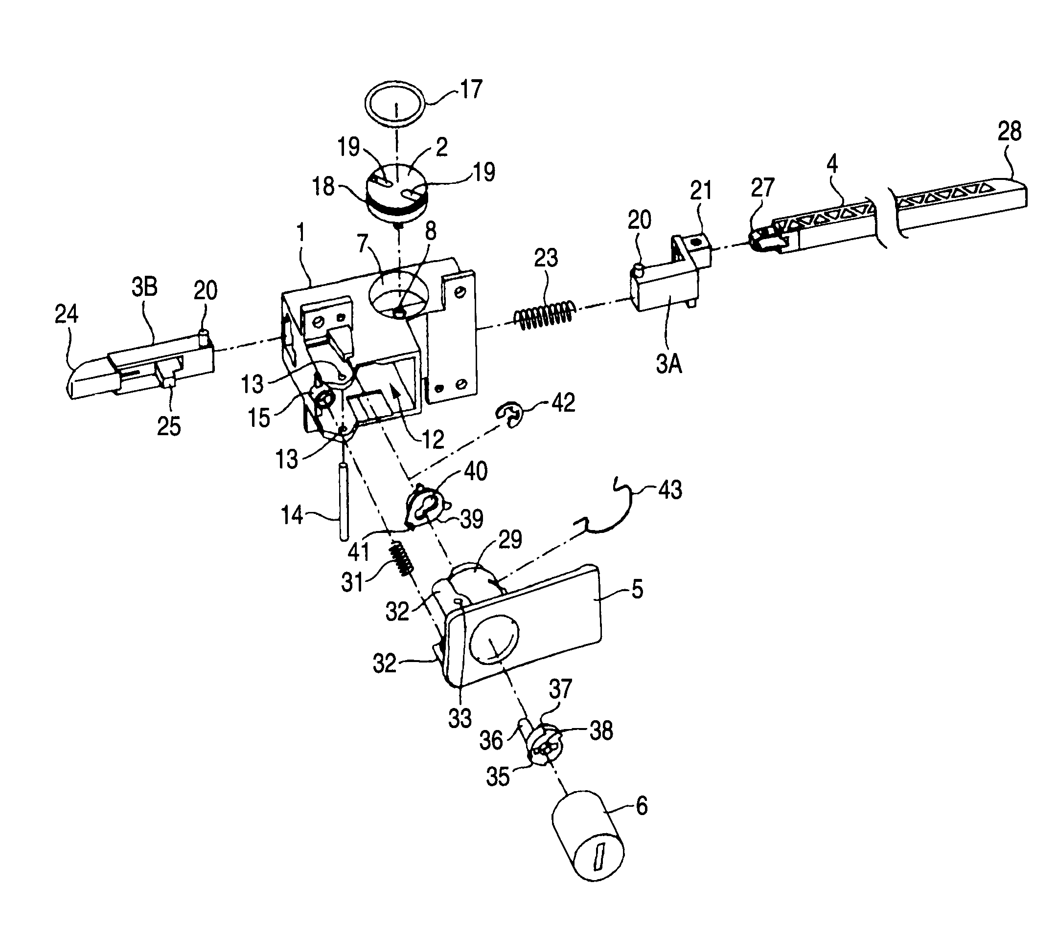
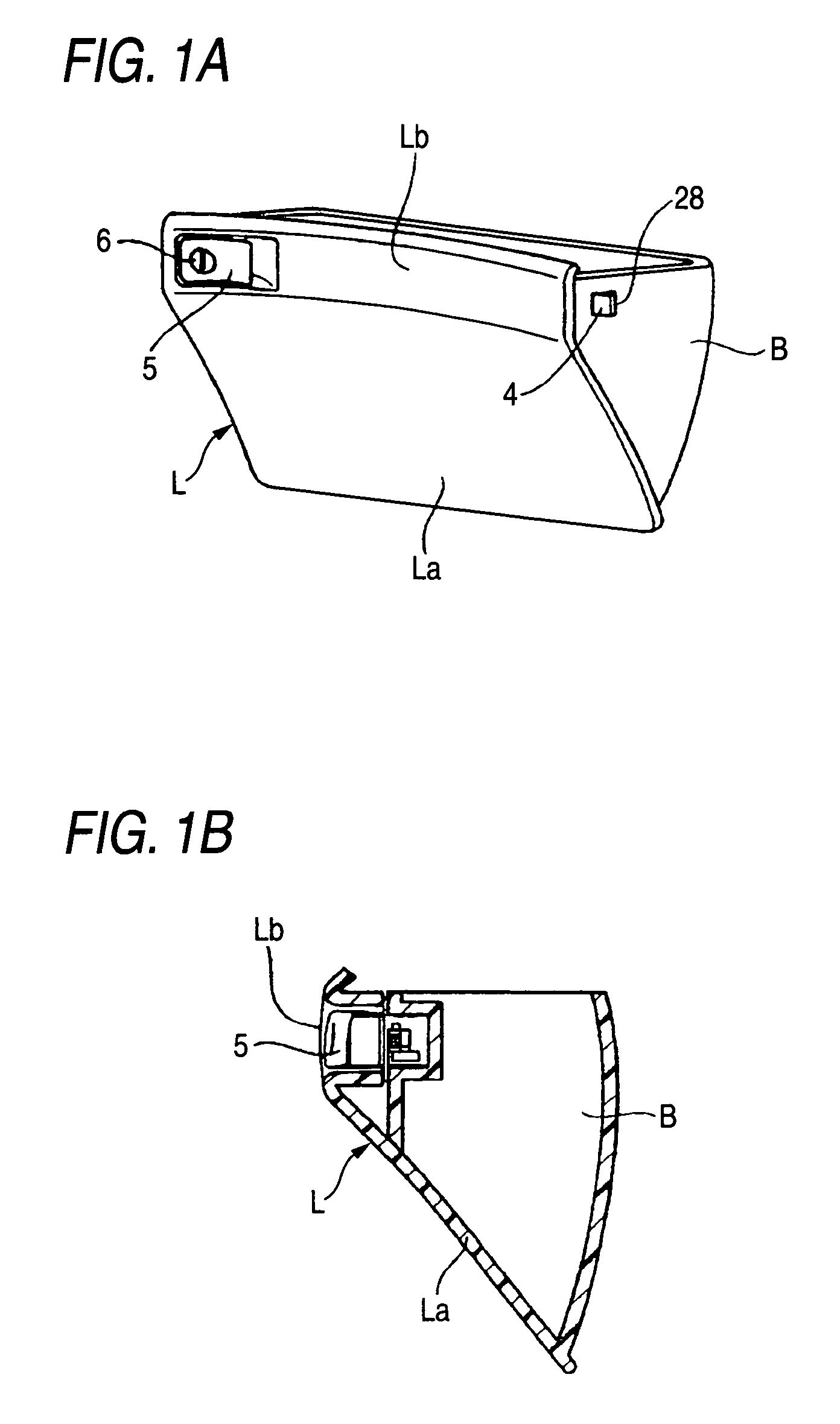
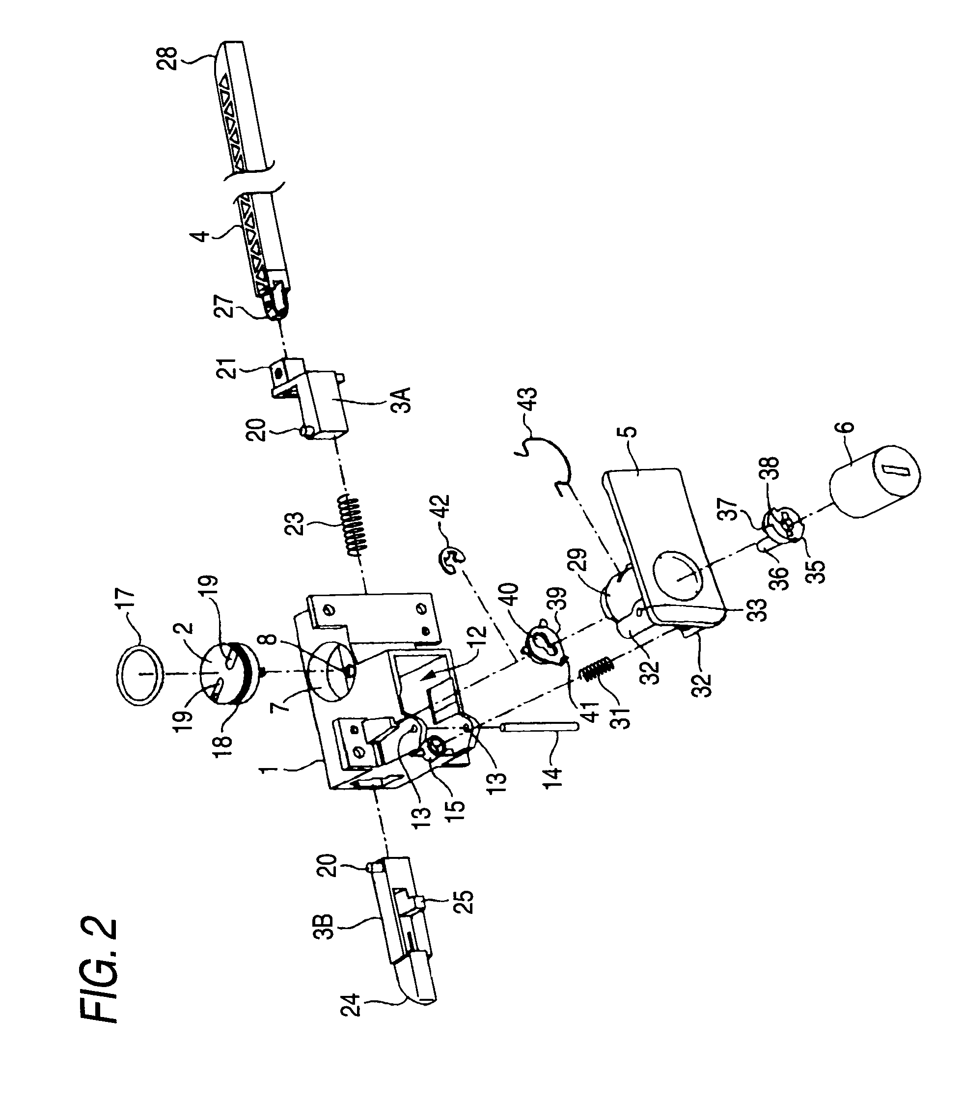
[0031]The invention is intended to provide an optimum side lock apparatus which is mounted on a rear side of a short upper portion of a lid for a glove box by providing a side lock apparatus for opening and closing a lid which has, as viewed in a vertical section, a long lower portion and a short upper portion which continues from the long lower portion in a bent fashion, including a housing which is fixed to a rear surface side of the short upper portion of the lid, a disc-shaped rotor which is rotatably supported on the housing, and a pair of left and right rods which are linked with the rotor in such a manner as to move back and forth as the rotor rotates, wherein the housing has a bearing portion for the rotor which is provided in such a manner as to extend vertically along the short upper portion of the lid and a first wall and a second wall which face the bearing portion while defining a space therebetween, the rotor is rotatably supported on the bearing portion in such a mann...


PUM


Abstract

A side lock apparatus includes: a housing which is fixed to a lid; a disc-shaped rotor which is supported on the housing; and rods which are linked with the rotor, wherein: the housing includes: a bearing portion for the rotor which is provided in such a manner as to extend vertically along the short upper portion of the lid; a first wall; a second wall; and a cylindrical portion which is brought into sliding contact with a disc-shaped outer circumferential surface of the rotor to support the rotor; the rotor is supported on the bearing portion in such a manner that the disc shape thereof becomes horizontal relative to a wall thickness direction of the short upper portion of the lid; and the rods are supported between the first wall and the second wall in such a manner as to slide in an opposite direction.

Description

BACKGROUND OF THE INVENTION[0001]1. Field of the Invention[0002]The present invention relates to a side lock apparatus for locking, for example, a glove box itself which is mounted in an instrument panel of a motor vehicle in such a manner as to be opened and closed or an independent lid thereof.[0003]2. Description of the Related Art[0004]Although not shown specifically, conventionally, a side lock apparatus of this type is constructed such that a pinion gear is rotatably supported within a housing which is fixed to a glove box main body's side, proximal end portions of a pair of left and right rods are provided in such a manner as to move back and forth, racks formed on surfaces of the proximal end portions of the rods are brought into mesh engagement with the pinion gear from opposite directions, while one of the rods is biased in a direction towards a lock hole opened in an instrument panel by virtue of a biasing spring pressure, and an operation knob is provided on a front surf...

Claims


Application Information

Patent Timeline
Patent Type & Authority Patents(United States)
IPC IPC(8): E05B13/10E05B83/30B60R7/06
CPCE05B83/30E05C1/145E05C9/042E05B13/101Y10T292/0926Y10T292/0913Y10T70/5761Y10T292/0834
Inventor OOKAWARA, TOSHIHIKOSHIMIZU, TOSHIHIRO
Owner PIOLAX CO LTD
Learn More