
Motor

a motor and motor body technology, applied in the field of motors, can solve the problems of increasing labor and increasing the size of the motor, and achieve the effects of suppressing the mounting space of electrical elements, increasing in size, and suppressing an increase in labor

Active Publication Date: 2018-02-20
DENSO CORP
View PDF4 Cites 0 Cited by
  • Summary
  • Abstract
  • Description
  • Claims
  • Application Information

AI Technical Summary

Benefits of technology

[0007]In consideration of the above particulars, the present disclosure provides a motor capable of suppressing the mounting space for electrical elements from increasing in size, while suppressing an increase in labor.
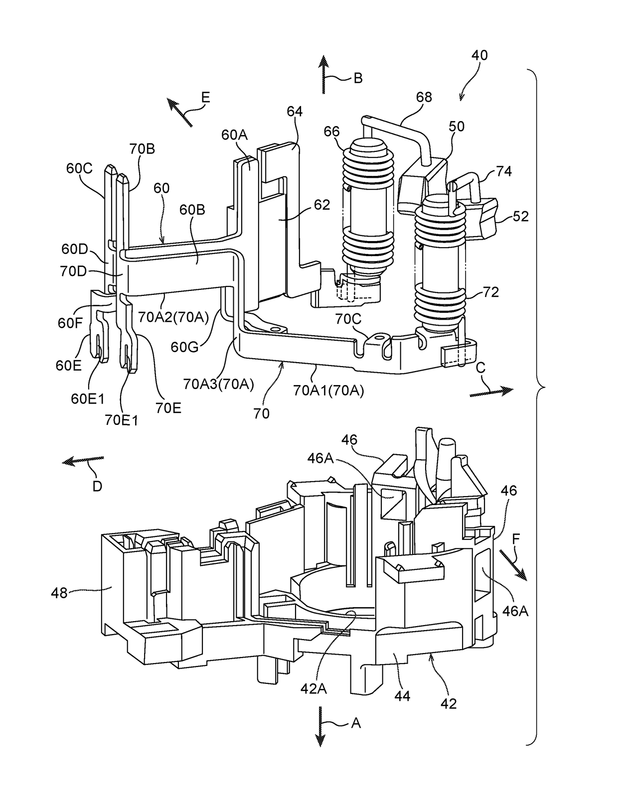
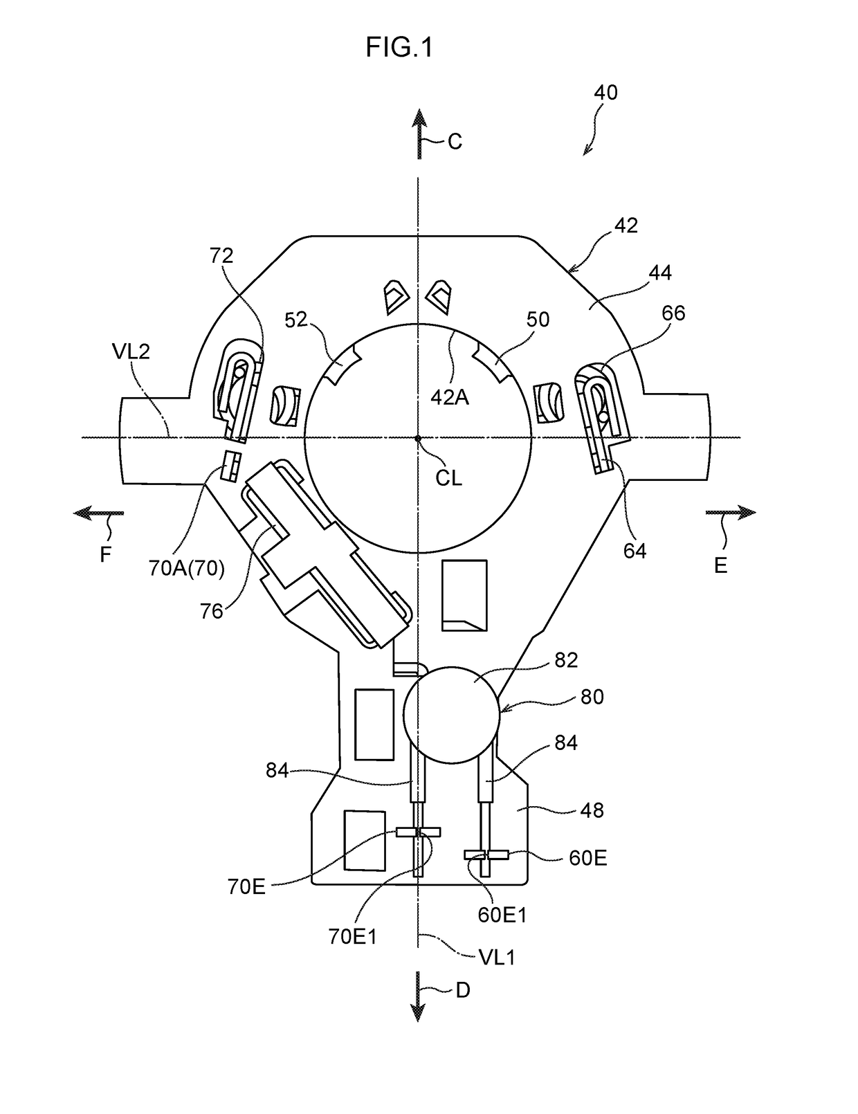
[0011]The pair of element connection portions are disposed offset from each other in the radial direction of the motor main body as viewed along the axial direction of the motor main body. Namely, the pair of element connection portions are disposed separated in the radial direction of the motor main body. The pair of element connection portions can thus be disposed corresponding to the distance between legs of the electrical element such that the pair of element connection portions do not interfere with each other. The need to bend the legs of the electrical element can thereby be dispensed with. Moreover, the mounting space for the electrical element or the pair of element connection portions can be made more compact than in cases in which the positions of the pair of element connection portions match in the radial direction of the motor main body.

Problems solved by technology

The need to bend the legs of the varistor results in increased labor, and there is a need for manage the angle, etc. of the bent legs.
Moreover, since the legs of the varistor are bent in a direction so as to separate away from each other, the mounting space of the varistor as viewed along the axial direction of the motor increases, leading to the motor increasing in size.

Method used


Image

  • Motor
  • Motor
  • Motor

Examples


Embodiment Construction

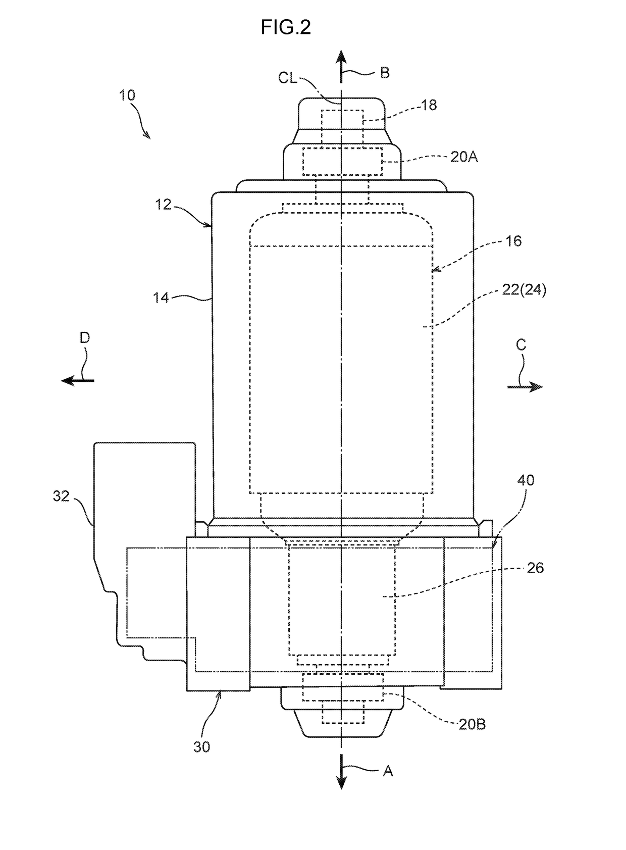
[0019]Explanation follows regarding a motor 10 according to an exemplary embodiment, with reference to the drawings. The motor 10 is, for example, employed as a drive source for a power window unit, a sunroof unit, or the like of a vehicle (automobile). As illustrated in FIG. 2, the motor 10 is configured including a motor main body 12 and a brush unit 40 provided at one axial direction side of the motor main body 12. Note that the arrow A illustrated in the drawings indicates one axial direction side of the motor main body 12, and the arrow B indicates the other axial direction side of the motor main body 12. In the following explanation, the one axial direction side of the motor main body 12 is denoted the lower side, and the other axial direction side of the motor main body 12 is denoted the upper side.

[0020]The motor main body 12 is configured as what is known as a brushed DC motor. The motor main body 12 includes a bottomed, substantially circular cylinder shaped motor yoke 14 ...


PUM


Abstract

There is provided a motor, the motor comprising (1) a brush unit that is provided at one axial direction side of a motor main body, and that includes a first brush and a second brush, (2) a pair of power supply terminals that are provided at the brush unit, that are respectively electrically connected to either the first brush or the second brush, and that include connector connection portions to which external connectors connect and that extend out toward another axial direction side of the motor main body at respective other end sides of the power supply terminals, and (3) a pair of element connection portions that are respectively provided at the other end sides of the power supply terminals, and that are disposed offset from each other in the radial direction of the motor main body.

Description

CROSS-REFERENCE TO RELATED APPLICATION[0001]This application claims priority under 35 USC 119 from Japanese Patent application No. 2015-036283 filed on Feb. 26, 2015, the disclosure of which is incorporated by reference herein.BACKGROUND[0002]Technical Field[0003]The present disclosure relates to a motor having a power supply terminal to which an electrical element is connected.[0004]Related Art[0005]In a motor described by Japanese Patent Application Laid-Open (JP-A) No. 2012-191792, pairs of terminals (power supply terminals) that supply electrical power to a brush from external connectors are configured as first terminals and second terminals, respectively. Moreover, an overvoltage suppressing varistor (electrical element) is connected across the first terminals out of the pairs of terminals.[0006]However, in the motor described by JP-A No. 2012-191792, the varistor (electrical element) is disposed at the radial direction outside of a rotation shaft of the motor. Moreover, the fi...

Claims


Application Information

Patent Timeline
Patent Type & Authority Patents(United States)
IPC IPC(8): H02K11/00H02K5/14H01R39/36H02K11/026
CPCH01R39/36H02K11/026H02K5/148
Inventor KITAI, TOSHIYUKI
Owner DENSO CORP
Learn More