
Optical device, optical unit and imager

a technology of optical units and optical devices, applied in the field of optical devices and optical units, can solve the problems of light scattering, difficult to move the lens within the imager, and the inability to arrange a massive motor or cam mechanism to drive the lens, etc., and achieve the effect of suppressing the performance from deterioration

Inactive Publication Date: 2008-05-20
FUJI PHOTO OPTICAL CO LTD
View PDF5 Cites 1 Cited by
  • Summary
  • Abstract
  • Description
  • Claims
  • Application Information

AI Technical Summary

Benefits of technology

[0012]It is an object of the present invention to provide an optical device, optical unit and imager that the refractive power is to be changed without restriction while suppressing the performance from deteriorating.
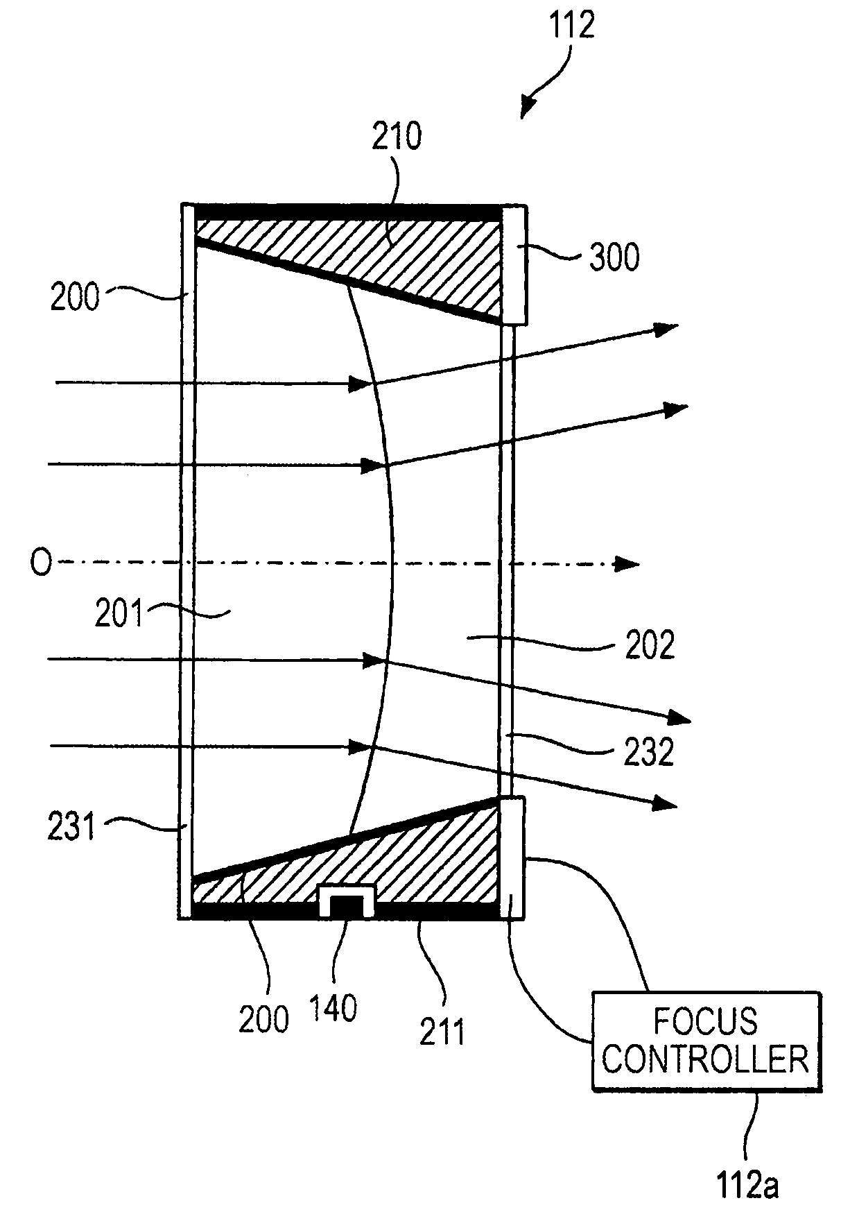
[0017]According to the optical device of the invention, by regulating the temperature of the coat film, the hydrophilic / hydrophobic property of the coat film is changed to change the form of the boundary plane of between the water-based liquid and the oil-based liquid. Recently, there is known a small-sized temperature regulator using a Peltier device or the like. By using such a small-sized temperature regulator, the refractive power on the optical device can be changed freely while suppressing the device from increasing in size. Meanwhile, according to the optical device of the invention, the boundary plane form of between the water-based liquid and the oil-based liquid is changed without releasing the charge to the water-based and oil-based liquids. This can avoid the disadvantage that the liquid is electrolyzed to cause bubbles, thus maintaining the optical-transmission property over a long term.
[0019]By contacting the first portion having a comparatively higher thermal conductivity with the coat film, the heat generated at the temperature regulator is efficiently transferred to the coat film. By covering the first portion with the second portion formed of a material having a comparatively lower thermal conductivity (i.e. heat-insulation material), the disadvantage the generated heat leaks can be prevented. Accordingly, the coat film is regulated with efficiency, thus accurately changing the boundary plane form of between the water-based liquid and the oil-based liquid.
[0021]Recently, a Peltier device (thermo-module) is known that utilizes the Peltier effect that, by supplying a current to a circuit joining together materials having different thermoelectric powers from each other, heat generation takes place at one point of the junctions thereof while heat absorption occurs at the other point (see the Internet <URL: http: / / www.scnt.co.jp / kakushin.pdf>, for example). According to the optical device in a preferred embodiment of the invention, the temperature of the coat film can be regulated by changing the direction and amount of current supply to the Peltier device, thus accurately controlling the refractive power of the optical device by means of a simple mechanism.
[0029]According to the optical unit of the invention, the refractive power can be changed freely wherein the optical transmission property can be maintained over a long term.

Problems solved by technology

However, in the small-sized imager for use in an endoscope, there is a difficulty in moving the lens within the imager or arranging a massive motor or cam mechanism to drive the lens.
Where used over a long term, the produced gas builds up into bubbles within the liquid container thus resulting in a problem that light scatter takes place to lower the transmittance of light.
This problem is generally true for the optical elements, such as parallel plates and prisms, without limited to the lens.

Method used


Image

  • Optical device, optical unit and imager
  • Optical device, optical unit and imager
  • Optical device, optical unit and imager

Examples


second embodiment

[0096]Completing the explanation on the first embodiment of the invention, explanation is now made on a second embodiment of the invention. the invention is the application of the image-taking apparatus of the invention to an endoscope, thus having an internal structure nearly similar to that of the digital camera of the first embodiment. Accordingly, the similar elements to those of the first embodiment are attached with the same reference numerals to omit the explanations thereof, in order to explain only the differences from the first embodiment.

[0097]FIG. 6 is a schematic structural view showing a tip of an endoscope 600 to which the second embodiment of the invention is applied.

[0098]The endoscope 600 has, at its tip, an insertion part 510, an operation part 520 connected to and for operating the insert part 510, and a cord 530 connected with a control section 540 (see FIG. 7) and a light source (not shown).

[0099]The insertion part 510 is structured with a tip portion 511 havin...


PUM


Abstract

An optical device comprises: a liquid container that contains water-based liquid and oil-based liquid that are different in refractive index from each other and immiscible with each other to have respective optical-transmission properties so that light can transmit in a predetermined optical-axis direction; a coat film that covers at least part of an inner surface of the liquid container and has a hydrophilic / hydrophobic property changing with temperature; and a temperature regulator that regulates temperature of the coat film.

Description

BACKGROUND OF THE INVENTION[0001]1. Field of the Invention[0002]The present invention relates to an optical device and optical unit transmissive of light, and to an imager capable of generating an image signal through focusing the light of from a subject.[0003]2. Description of the Related Art[0004]Recently, it is popular to incorporate an imager, capable of acquiring a digital photographic image by taking a picture of a subject, in a small-sized appliance such as a cellular phone or a PDA (personal digital assistant). By providing an imager on a small-sized appliance carried at all times, shooting is available at any time in a manner freely from carrying a digital or video camera in the related art.[0005]Meanwhile, the endoscope is usually used at the medical site, to insert a small-sized imager in the body cavity and take images of the body interior. It is a recent practice to excise, at the site, a lump, etc. found upon photographing, by use of the excision tool attached on the e...

Claims


Application Information

Patent Timeline
Patent Type & Authority Patents(United States)
IPC IPC(8): G02B1/06
CPCG02B3/14G02B7/028G02B13/0075G02B13/009G02B26/005H04N5/217H04N5/2254H04N2005/2255H04N23/81H04N23/555H04N23/673
Inventor KOHNO, SHINICHI
Owner FUJI PHOTO OPTICAL CO LTD
Learn More