
Actuator

a technology of actuators and actuators, applied in the direction of bearing units, bearings, rigid supports, etc., can solve the problems of increasing the size of the speed reduction mechanism, increasing the frame size of the actuator provided, and increasing the size of the actuator in the axial direction, so as to achieve the effect of suppressing the increase in the radial direction of the actuator

Active Publication Date: 2017-06-29
DENSO CORP
View PDF7 Cites 0 Cited by
  • Summary
  • Abstract
  • Description
  • Claims
  • Application Information

AI Technical Summary

Benefits of technology

[0010]According to the actuator of the first aspect, the rotation shaft side gear rotates when the rotation shaft of the motor rotates. Moreover, when the rotation shaft side gear rotates, the first intermediate gear, which meshes with the rotation shaft side gear, rotates together with the second intermediate gear. Namely, the intermediate gear configuration body rotates. Moreover, the output shaft side gear, which meshes with the second intermediate gear of the intermediate gear configuration body, rotates when the intermediate gear configuration body rotates. The output shaft is thereby rotated. In configurations in which an intermediate gear configuration body is cantilever-supported, in order to suppress center misalignment of the intermediate gear configuration body during operation of the actuator, it is conceivable that an increase in the thickness of a portion supporting the intermediate gear configuration body will be necessary, or an increase in rigidity will be necessary, such as by increasing the diameter of the intermediate gear configuration body. However, in the present aspect, the end portion at the first intermediate gear side and the end portion at the second intermediate gear side of the intermediate gear configuration body are supported by the first bearing and the second bearing, respectively. Namely, the intermediate gear configuration body is supported at both ends by the first bearing and the second bearing. This suppresses an increase in the size of portions of the intermediate gear configuration body, or suppresses the intermediate gear configuration body from becoming larger in the radial direction compared to configurations in which the intermediate gear configuration body is cantilever-supported. The present aspect can thereby suppress the frame of the actuator from increasing in size.
[0034]According to the actuator of the thirteenth aspect, an increase in the radial direction size of the actuator can be suppressed due to disposing the component attached to the circuit board and the output shaft side gear so as to overlap with each other as viewed along the axial direction of the output shaft.

Problems solved by technology

This would increase the size of the speed reduction mechanism and increase the frame size of the actuators provided with this speed reduction mechanism.
However, in such cases, it is necessary to provide a circuit board mounted with an element for detecting the magnetic field of the sensor magnet at one axial direction side of the output shaft, increasing the size of the actuator in its axial direction.

Method used


Image

  • Actuator
  • Actuator
  • Actuator

Examples


Embodiment Construction

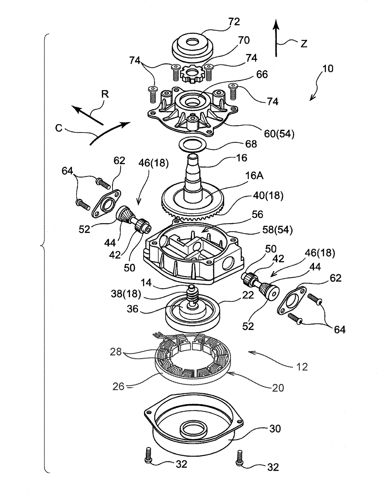
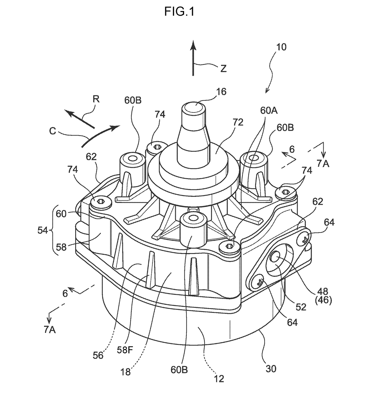
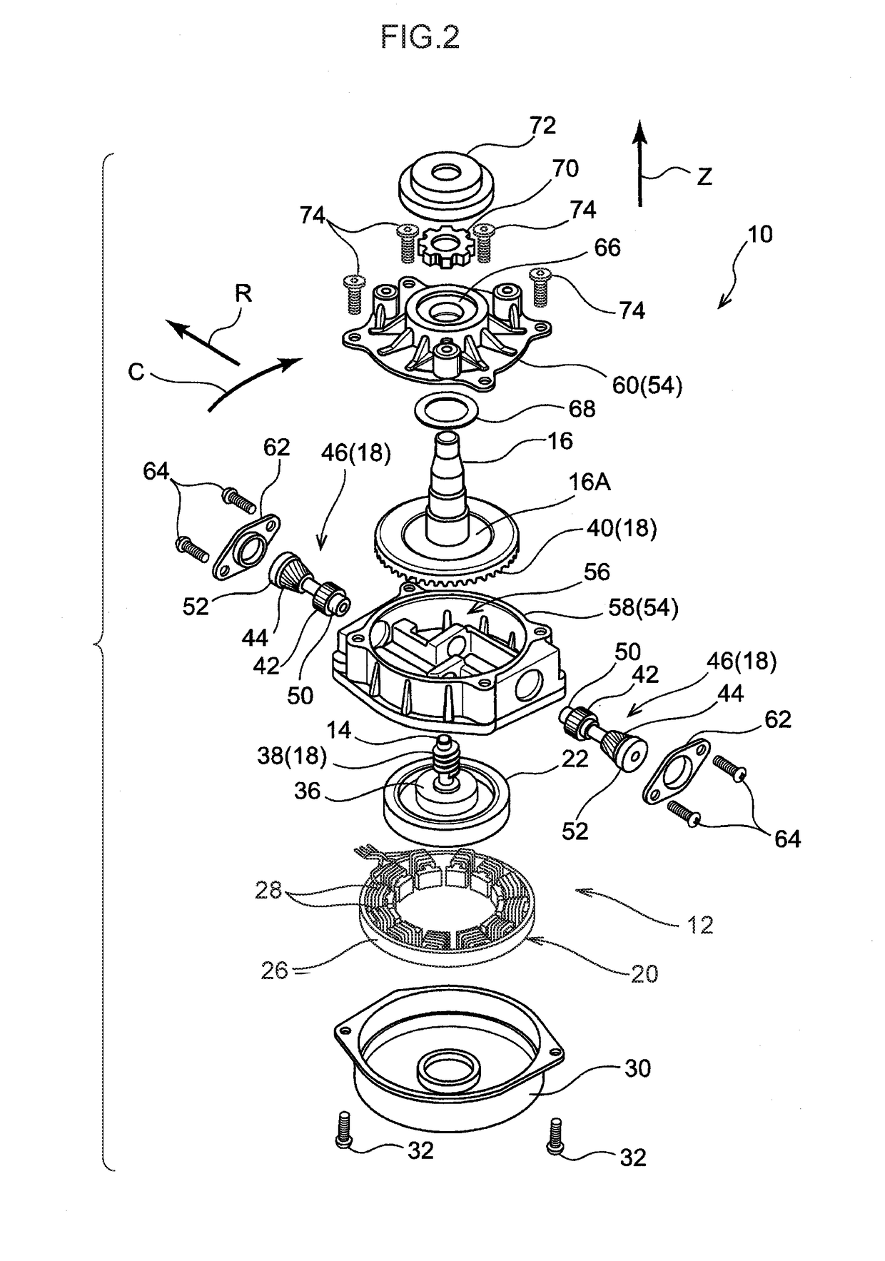
[0048]Explanation follows regarding an actuator 10 according to an exemplary embodiment of the present invention, with reference to FIG. 1 to FIG. 8A. Note that in the drawings, the arrow Z direction, the arrow R direction, and the arrow C direction respectively indicate the axial direction, the radial direction, and the circumferential direction of a motor 12 configuring a portion of the actuator, as appropriate. Moreover, hereafter, references simply to the axial direction, radial direction, and circumferential direction, refer to the axial direction, the radial direction, and the circumferential direction of the motor 12, unless otherwise stated. Moreover, the axial direction, radial direction, and circumferential direction of the motor 12 respectively correspond to the axial direction, radial direction, and circumferential direction of a rotation shaft 14 of the motor 12 and an output shaft 16 of the actuator 10.

[0049]As illustrated in FIG. 1 and FIG. 2, the actuator 10 of the p...


PUM


Abstract

An actuator includes a motor having a rotation shaft, and an output shaft disposed coaxially to the rotation shaft. A rotation shaft side gear is provided so as to be rotatable as a unit with the rotation shaft, and an output shaft side gear is provided so as to be rotatable as a unit with the output shaft. An intermediate gear configuration body is provided between the rotation shaft side gear and the output shaft side gear. The intermediate gear configuration body includes a first intermediate gear that meshes with the rotation shaft side gear, and a second intermediate gear that is provided so as to be rotatable as a unit with the first intermediate gear and that meshes with the rotation shaft side gear. A detected portion is provided at an end portion of the intermediate gear configuration body and detects a rotation speed of the intermediate gear configuration body. A detecting portion detects the detected portion. The rotation shaft side gear, the first intermediate gear, the second intermediate gear, and the output shaft side gear are housed inside a gear housing that is disposed at one side in an axial direction of the motor, and the detecting portion is disposed outside of the gear housing.

Description

CROSS-REFERENCE TO RELATED APPLICATIONS[0001]This application is a continuation application of, and claims the benefit of, U.S. application Ser. No. 14 / 953,019, filed on Nov. 27, 2015, which claims priority under 35 U.S.C. §119 from Japanese Patent Application No. 2014-243338, filed on Dec. 1, 2014, Japanese Patent Application No. 2014-243339, filed on Dec. 1, 2014, and Japanese Patent Application No. 2015-217713, filed on Nov. 5, 2015. The disclosures of all of the above-identified applications are incorporated by reference herein in their entireties.BACKGROUND[0002]Technical Field[0003]The present invention relates to an actuator.[0004]Related Art[0005]Japanese National-Phase Publication No. 2003-529731 describes an actuator provided with a speed reduction mechanism, and this actuator includes a DC motor and a speed reduction mechanism that transmits to an output shaft with a rotation speed about a rotation shaft of the DC motor reduced by a specific speed reduction ratio. Moreove...

Claims


Application Information

Patent Timeline
Patent Type & Authority Applications(United States)
IPC IPC(8): F16H1/14F16H1/20H02K21/14F16C19/54F16C35/067H02K7/116F16H1/22F16H57/021
CPCF16H1/145F16H1/225F16H1/203F16H57/021F16C2361/61F16C35/067H02K7/1163H02K21/14F16C19/543F16C19/06G01R33/07F16H1/222H02K7/1166G01B7/14
Inventor OKADA, SHINICHIITO, YASUHIDESHIBATA, KOHEINEGI, TAKAFUMI
Owner DENSO CORP
Learn More