
Enteral feeding catheter device with an indicator

a technology of a catheter and an indicator, which is applied in the field of balloon catheters, can solve the problems of balloons that may eventually leak and deflate, change the dimensions of balloons, tissue damage, etc., and achieve the effect of increasing inflation pressur

Active Publication Date: 2012-03-27
AVENT INC
View PDF45 Cites 23 Cited by
  • Summary
  • Abstract
  • Description
  • Claims
  • Application Information

AI Technical Summary

Benefits of technology

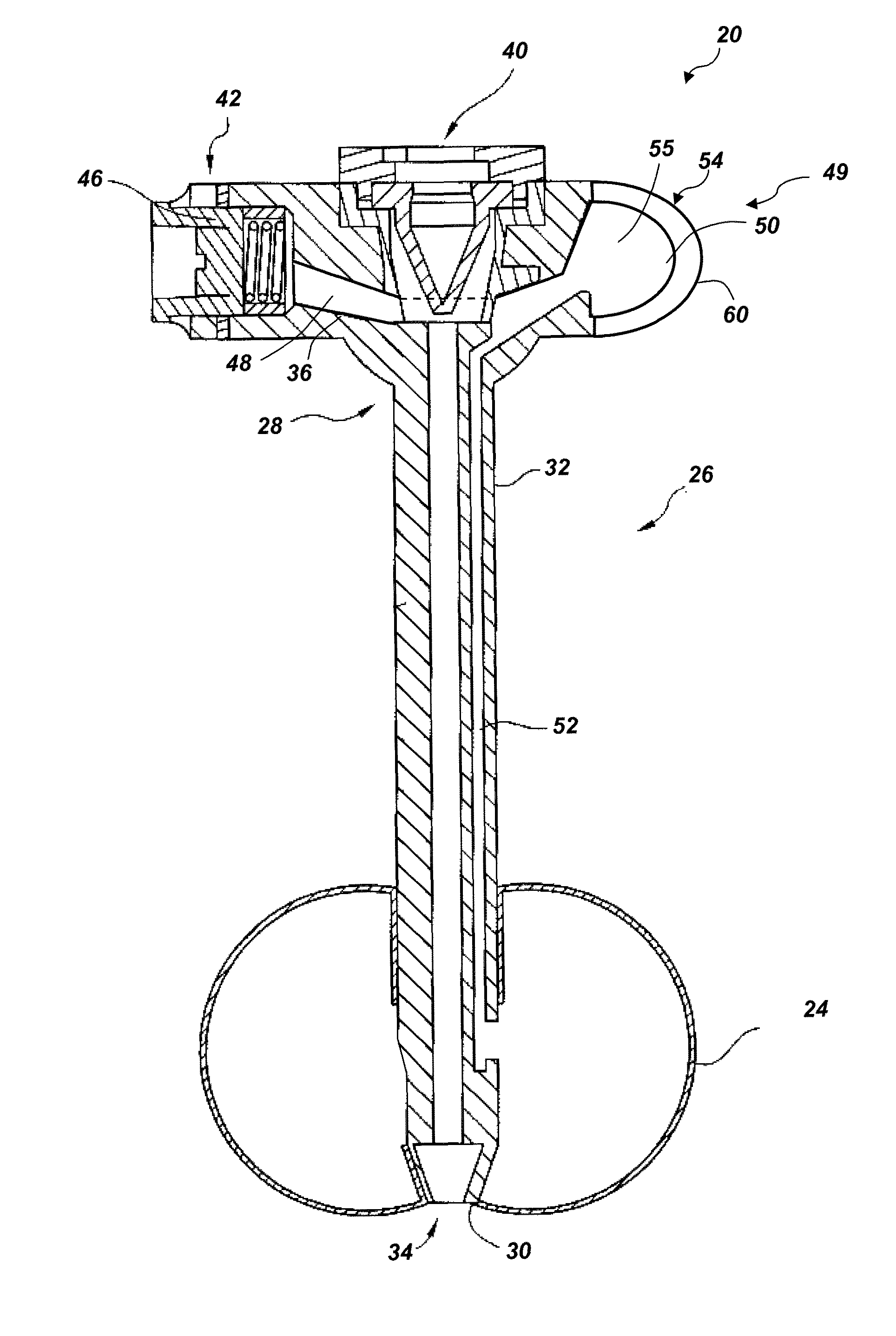
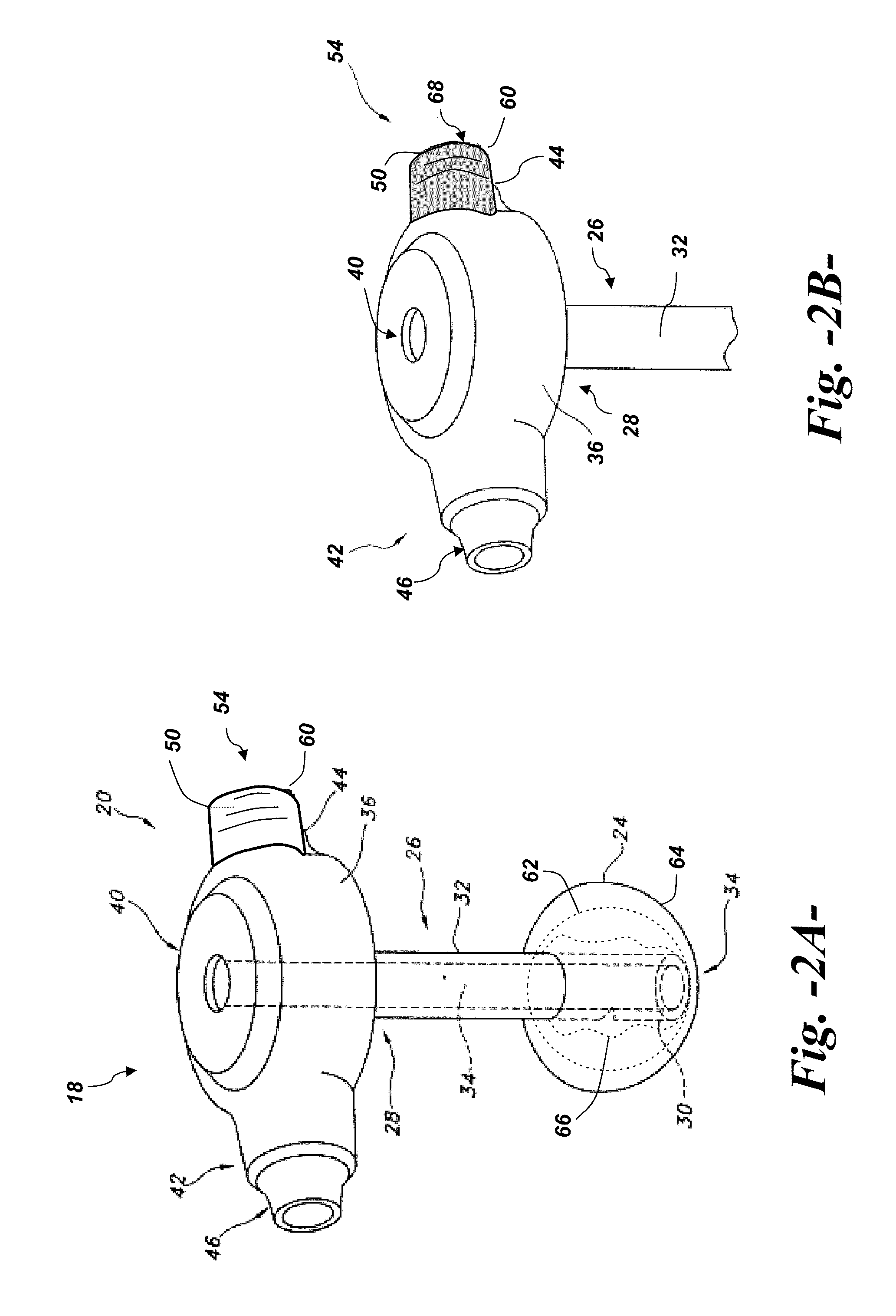
[0015]According to an aspect of the invention, the balloon catheter device may be an enteral feeding catheter that includes a catheter having a proximal end, a distal end, and catheter walls defining a catheter lumen. A base is located at the proximal end of the catheter. An opening to the catheter lumen is defined in the base. The base may be variously configured with any desired shape or profile, and in one embodiment has a first end and a second end. An inflatable balloon is located at a distal end of the catheter. In one embodiment, the balloon may be an elastomeric balloon that stretches and expands generally continuously with increasing inflation pressure from an initial un-inflated state to an operational fill volume. In an alternate embodiment, the balloon may be configured with a collapsed, non-distended state and expands with negligible inflation pressure to an initial distended state in which the material that forms the balloon is smooth and completely unfolded but prior to any meaningful stretching of the material. The balloon is then further pressurized with fluid to an operational fill volume that is generally no more than about 1.5 times (i.e., about 50 percent greater than) the volume of the balloon at its initial distended state.

Problems solved by technology

While these balloons have many advantages, balloons may eventually leak and deflate.
In addition, “soft” or elastomeric medical grade silicone has a tendency to “creep” or stress relax over time which can change the dimensions of the balloon.
In order to adequately seal the space between the lumen of the trachea and the balloon, there is a tendency to overinflate the balloon, which may result in tissue damage.
If the pressure is too low, the balloon does not adequately seal the space between the lumen of the trachea and the balloon thereby allowing secretions to enter the lungs causing pneumonia and other respiratory complications.
While this level of sensitivity and continuous reading is desirable, pilot balloons and similar bellows or diaphragm indicators are relatively large and typically require skill and experience to accurately interpret the output of these conventional devices as they provide a continuous reading of pressure.
While electronic pressure sensors are accurate and are generally easy to read, they are relatively large and expensive.
Scaling these types of devices down to a sufficiently small size so they can be used with a low-profile PEG tube only highlights the problems associated with the size, calibration, accuracy, and reading or interpreting the output of these devices.
The device of Fournie et al. is relatively complicated and adds significantly to the manufacturing process and costs.
In addition, the indicator increases the overall profile (i.e., shape, height, etc.) of the head, which is generally undesirable to the user.
In addition, the use of moving, mechanical indicator components is always prone to failure or malfunction of such components, which results in a complex medical procedure to replace the device.

Method used


Image

  • Enteral feeding catheter device with an indicator
  • Enteral feeding catheter device with an indicator
  • Enteral feeding catheter device with an indicator

Examples


Embodiment Construction

[0034]Reference will now be made in detail to one or more embodiments of the invention, examples of the invention, examples of which are illustrated in the drawings. Each example and embodiment is provided by way of explanation of the invention, and is not meant as a limitation of the invention. For example, features illustrated or described as part of one embodiment may be used with another embodiment to yield still a further embodiment. It is intended that the invention include these and other modifications and variations as coming within the scope and spirit of the invention.

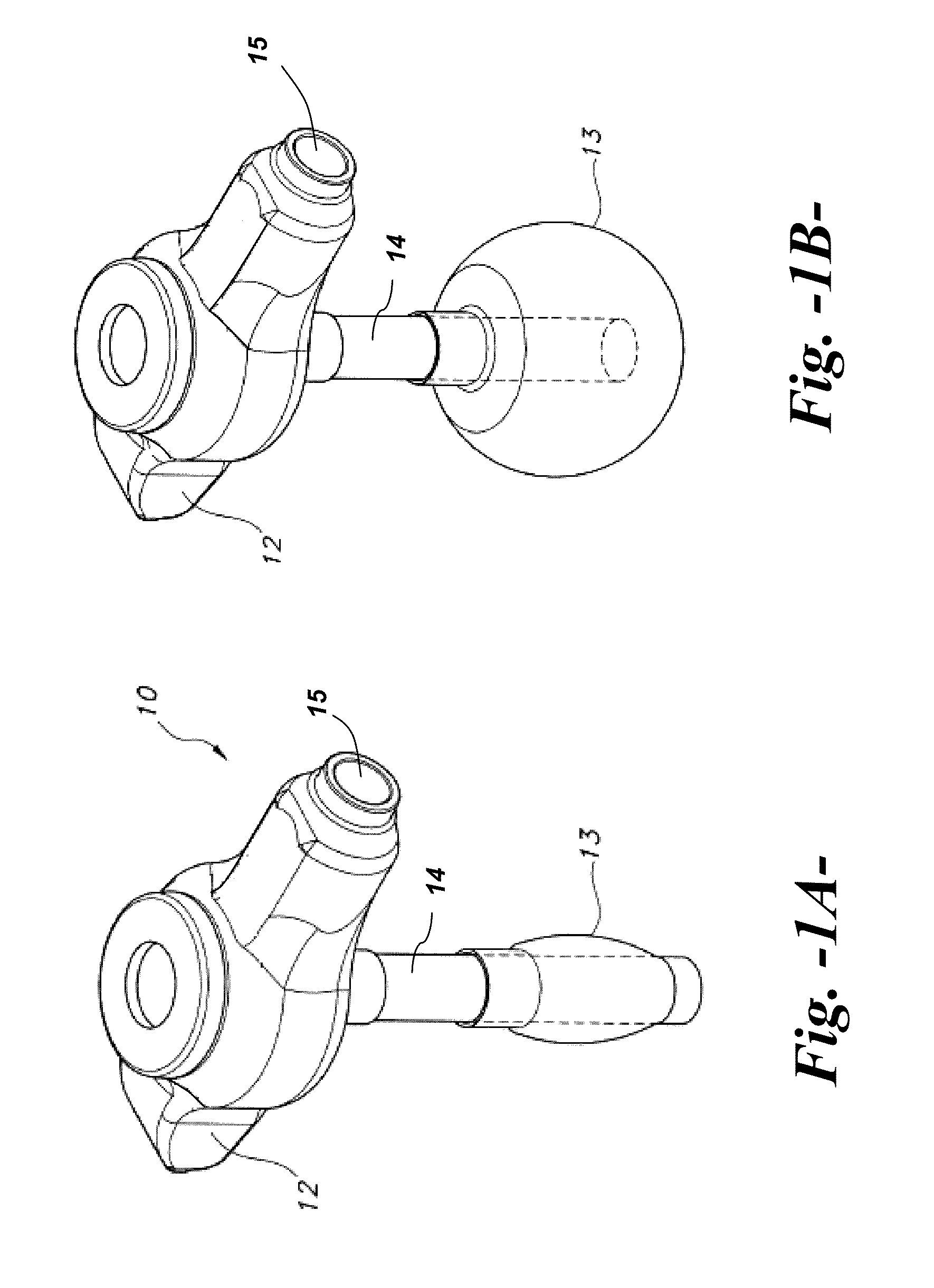
[0035]FIGS. 1A and 1B are views of a conventional PEG tube device 10 having a base 12 and retainer balloon 13 made of conventional “soft” or elastomeric medical grade silicone in an un-stretched state (i.e., un-inflated condition) at the distal end of a catheter shaft 14. In FIG. 1B, the balloon 13 has been stretched by inflation to an inflated operational fill volume. As is well understood by those skilled i...


PUM


Abstract

A balloon catheter device, for example an enteral feeding catheter, includes a catheter having a proximal end, a distal end, and catheter walls defining a catheter lumen. A base is located at the proximal end of the catheter and has an opening to the catheter lumen. An inflatable balloon is located at a distal end of the catheter and is inflated through an inflation valve located on the base. An internal cavity is defined in the base and is in fluid communication with the inflatable balloon such that fluid used to inflate the balloon to an operational fill volume fills the internal cavity as well. A translucent window is disposed over the internal cavity such that an interior volume of the cavity is externally viewable. Introduction of a colored fluid through the inflation valve to inflate the balloon results in the colored fluid also being present in the internal cavity, thereby providing an externally visual indication of the inflation state of the balloon.

Description

FIELD OF THE INVENTION[0001]The present invention relates generally to balloon catheters, and more particularly to improved gastrostomy tubes or enteral feeding catheters.BACKGROUND[0002]Numerous situations exist in which a body cavity needs to be catheterized to achieve a desired medical goal. One relatively common situation is to provide nutritional solutions or medicines directly into the stomach or intestines. A stoma is formed in the stomach or intestinal wall and a catheter is placed through the stoma. This surgical opening and / or the procedure to create the opening is common referred to as “gastrostomy”. Feeding solutions can be injected through the catheter to provide nutrients directly to the stomach or intestines (known as enteral feeding). A variety of different catheters intended for enteral feeding have been developed over the years, including some having a “low profile” relative to the portion of the catheter which sits on a patient's skin, as well as those having the ...

Claims


Application Information

Patent Timeline
Patent Type & Authority Patents(United States)
IPC IPC(8): A61M29/00A61F2/958
CPCA61J15/0042A61J15/0065A61M25/1018A61J15/0015A61J2015/0088A61J15/0088A61M25/10187A61M25/10181A61M2210/1042
Inventor ROTELLA, JOHN A.HERSHEY, ADRIENNE A.MCMICHAEL, DONALD J.
Owner AVENT INC
Learn More