Pre-applied protective jacketing to grooved insulation
a protective jacketing and groove technology, applied in the direction of pipes, building components, synthetic resin layered products, etc., can solve the problems of reducing the cost and installation time, lack of protective jacketings, and the inability to manufacture known grooved insulation members, so as to achieve convenient application and save shipping costs , the effect of economic benefits
- Summary
- Abstract
- Description
- Claims
- Application Information
AI Technical Summary
Benefits of technology
Problems solved by technology
Method used
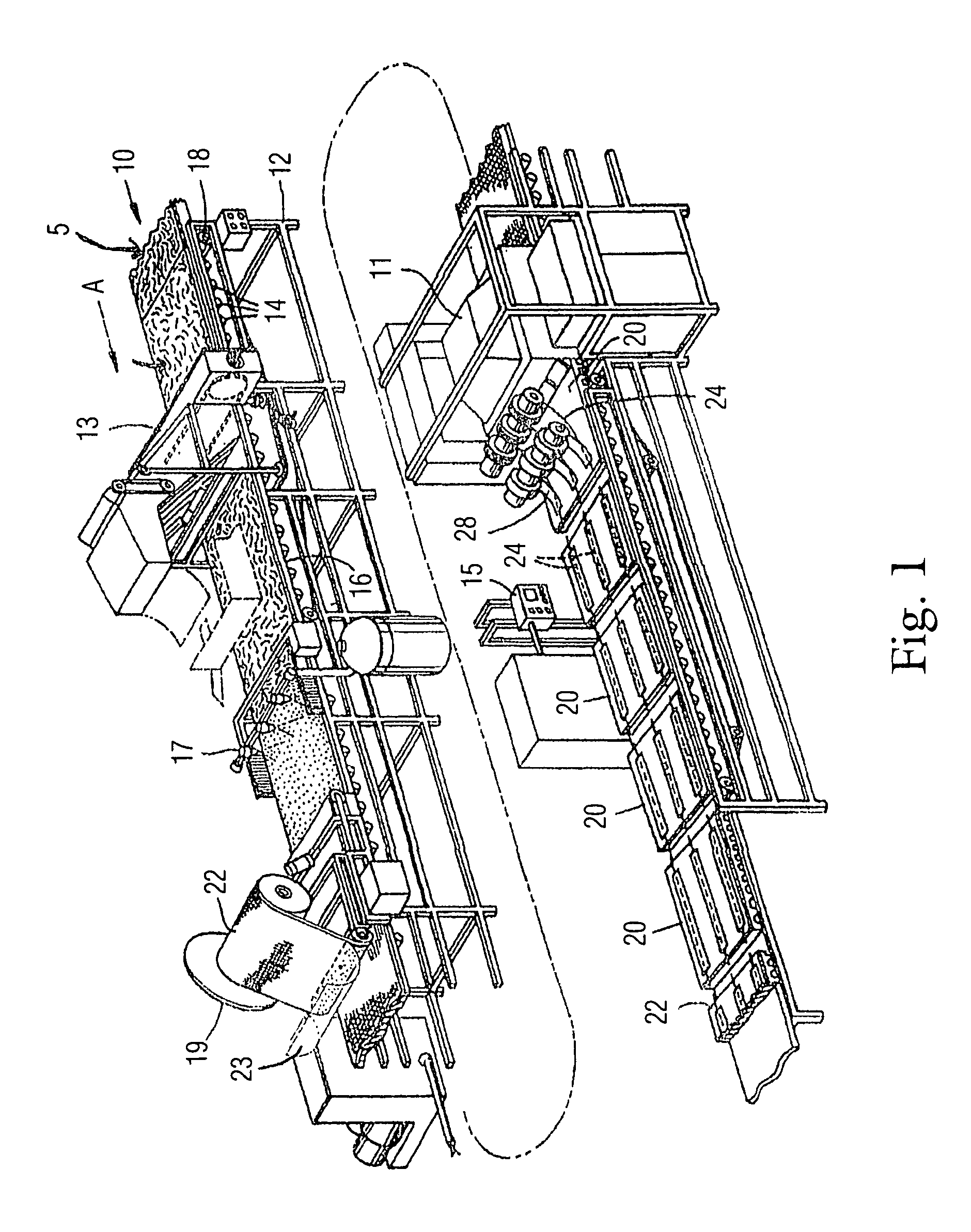
Image

Examples
Embodiment Construction
Definitions
[0026]“Insulating materials” as used herein means a material having low heat conductivity and an ability to withstand high temperatures without degradation or destruction.
[0027]“Rigid,” as used herein, defines a structure which will not, without modification (e.g., an initial application of force), adapt to a shaped surface.
[0028]“Adhesive Layer,” or “adhesive coating,” as used herein, refers to any adhesive once disposed on the insulation substrate and in this regard have the same meaning. The protective jacketing described herein is associated with an adhesive which is separate from the adhesive on the insulation substrate.
[0029]“Multiform insulation,” as used herein, refers to two dissimilar insulating materials which can make up an insulation member.
[0030]“Composite insulation,” refers to one or more insulation members including an adhesive layer joined to a protective jacketing, and optionally an additional backing member.
[0031]“Protective jacketing material,”“Protec...
PUM
| Property | Measurement | Unit |
|---|---|---|
| width | aaaaa | aaaaa |
| thickness | aaaaa | aaaaa |
| thickness | aaaaa | aaaaa |
Abstract
Description
Claims
Application Information
 - R&D
- Intellectual Property
- Life Sciences
- Materials
- Tech Scout
- Unparalleled Data Quality
- Higher Quality Content
- 60% Fewer Hallucinations
Browse by: Latest US Patents, China's latest patents, Technical Efficacy Thesaurus, Application Domain, Technology Topic, Popular Technical Reports.
© 2025 PatSnap. All rights reserved.Legal|Privacy policy|Modern Slavery Act Transparency Statement|Sitemap|About US| Contact US: help@patsnap.com