To planar antennas comprising at least one radiating element of the longitudinal radiation slot type

a technology of longitudinal radiation slot and radiating element, which is applied in the direction of slot antenna, antenna details, antennas, etc., can solve the problems of increasing complexity and effectiveness, reducing the radiation of the antenna, and keeping the manufacturing cost as low

Inactive Publication Date: 2012-03-27
THOMSON LICENSING SA
View PDF4 Cites 13 Cited by
  • Summary
  • Abstract
  • Description
  • Claims
  • Application Information

AI Technical Summary

Problems solved by technology

The increasing development of communication systems, notably wireless, requires the use of increasingly complex and effective systems, while keeping manufacturing costs as low as possible and a minimum size.
However, with regard to the radiating elements, a planar structure does not enable a full control of the radiation of the antenna, particularly in elevation.

Method used


Image

  • To planar antennas comprising at least one radiating element of the longitudinal radiation slot type
  • To planar antennas comprising at least one radiating element of the longitudinal radiation slot type
  • To planar antennas comprising at least one radiating element of the longitudinal radiation slot type

Examples


Embodiment Construction

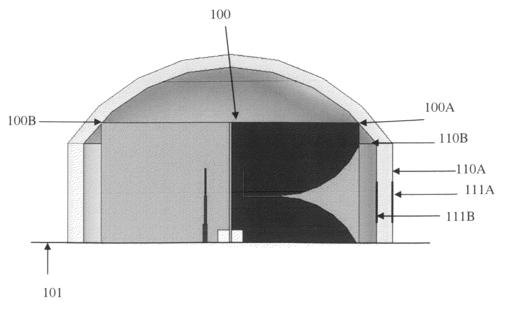
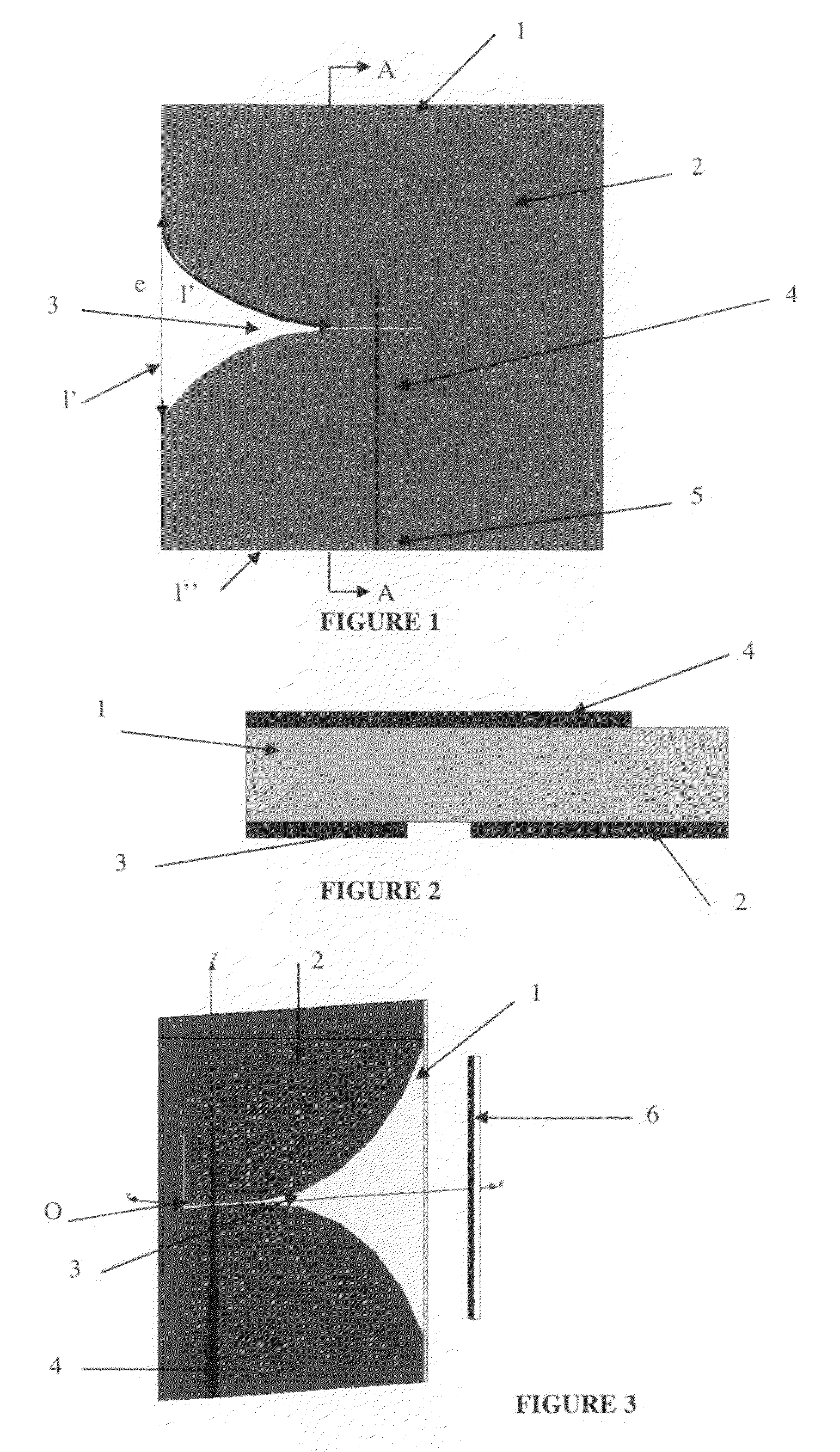
[0035]The present invention will be described by taking as radiating element constituted by a longitudinal radiation slot, an LTSA (Linearly Tapered Slot Antenna) type antenna such as a Vivaldi antenna. It is evident that the invention can be applied to other types of longitudinal radiation antennas.

[0036]As shown in FIGS. 1 and 2, an antenna of this type is obtained by etching on a substrate 1, a slot 3 that gradually enlarges up to an edge 1′ of the substrate. On the other side of the substrate 1, a microstrip line 4 is etched enabling the excitation by electromagnetic coupling of said slot. Other types of feed can be considered without leaving the scope of the invention, particularly a feed by coplanar line.

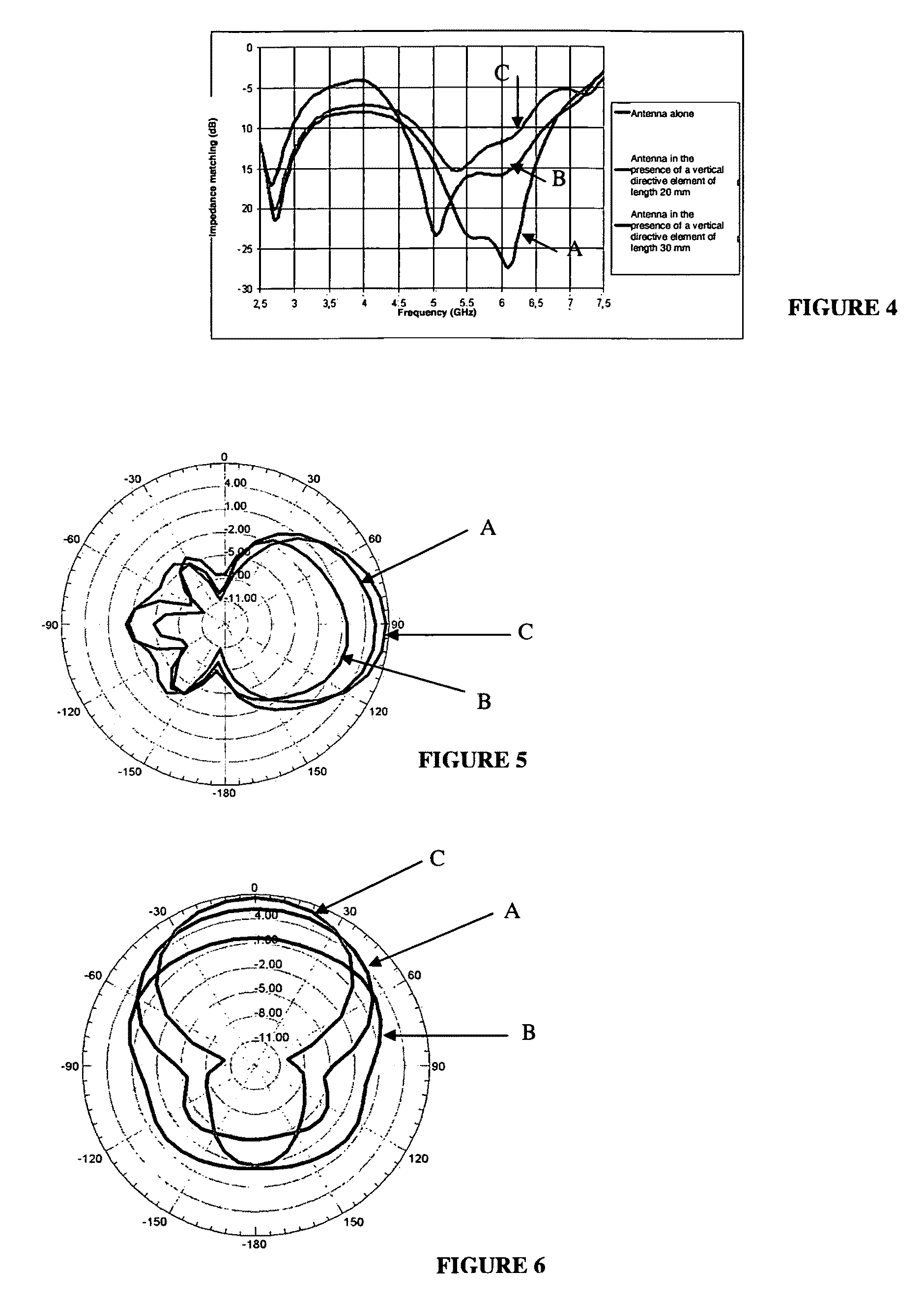
[0037]As shown in FIG. 1, the excitation line 4 is extended up to one 1″ of the edges of the substrate 1 to obtain an access point 5. This type of antenna gives an excellent impedance matching over a wide frequency band. Hence, it has been shown that, according to a first appr...


PUM


Abstract

The present invention relates to a planar antenna structure comprising at least one radiating element constituted by a longitudinal radiation slot etched onto a substrate. This structure comprises at least one modification element of the radiation pattern positioned in the radiation zone of the radiating element.

Description

[0001]This application claims the benefit, under 35 U.S.C. §119, of European Patent Application No. 0850173 of 11 Jan. 2008.FIELD OF THE INVENTION[0002]The present invention relates to an improvement to planar antennas, more particularly to antennas comprising at least one radiating element constituted by a longitudinal radiation slot.BACKGROUND OF THE INVENTION[0003]The increasing development of communication systems, notably wireless, requires the use of increasingly complex and effective systems, while keeping manufacturing costs as low as possible and a minimum size. Now, in this domain, the antennas represent an exception to this possibility of miniaturisation. Indeed, they are subject to the laws of physics that impose a minimum size for operation at a given frequency. Hence, for printed planar antennas, the dimensions are generally in the order of the wavelength at the central operating frequency.[0004]However, it is certain the printed planar structures are structures perfec...

Claims


Application Information

Patent Timeline
Patent Type & Authority Patents(United States)
IPC IPC(8): H01Q13/10H01Q1/42
CPCH01Q1/38H01Q1/42H01Q13/085H01Q19/28H01Q21/20H01Q25/005
Inventor THEVENARD, JULIANLO HINE TONG, DOMINIQUELOUZIR, ALINICOLAS, CORINNECOUPEZ, JEAN-PHILIPPEPERSON, CHRISTIAN
Owner THOMSON LICENSING SA
Why Eureka
Try Eureka