Integrated feature for friction less movement of force sensitive touch screen

a touch screen and friction-less technology, applied in the direction of electrical apparatus construction details, instruments, casings/cabinets/drawers, etc., can solve the problems of mechanical implementation, difficult to produce high-quality touch screen solutions, and problems that must be overcome, so as to reduce the dependency on extremely tight mechanical tolerances

Active Publication Date: 2012-03-27
APPLE INC
View PDF49 Cites 111 Cited by
  • Summary
  • Abstract
  • Description
  • Claims
  • Application Information

AI Technical Summary

Benefits of technology

[0027]Another important object of this invention is to reduce the dependency on extremely tight mechanical tolerances by preloading the sensor.
[0028]In accordance with the foregoing objects, the present invention is a touch input comprising a touch lens suspended over force sensors by a new and innovative suspension mechanism, for use in either fixed or mobile devices such as point of sales terminals, kiosks, laptops, monitors, PDAs, cell phones, UMPCs and more. The suspension mechanism is scalable and can be varied in size and pre-loading pressure. The solution can also be manufactured at high volumes and at a low cost and is suitable for touch screen based products ranging from cellular phones and personal digital assistance up to computer monitors and plasma TVs / Monitors. The touch sensitive lens may also be either a separate touch lens made out of plastic or computer glass, or it may be the actual display module.
[0030]Alternative implementation and manufacturing methods of the above described figure 8-loop suspension system is disclosed one in which the suspension wire is threaded through holes. This manufacturing method not only reduces the manufacturing costs, but also optimizes the performance of the suspension mechanism.
[0031]Other alternative implementations include continuous suspension, bender suspension and 3-dimensional force suspension. As further described below, these suspension methods also ensures friction-free or close to friction-free movement in the z-plane while locking the lens in the xy-plane and thereby ensuring no movement or introduction of unknown forces to the system.
[0032]Another important improvement lies in the use of a flexible padding between the rigid back plane and the sensor allowing the sensor to be slightly compressed, e.g., preloaded, which reduces the dependency on extremely tight mechanical tolerances.

Problems solved by technology

The concept of using multiple force sensing sensors to register, measure and triangulate the touched position of a touch screen has been a known concept for more then twenty years, however, to produce a high quality touch screen solution has proven difficult.
There is however still one major problem that must be overcome, the mechanical implementation.
Until now, production of force based touch screen devices with high accuracy has been a challenge due to large errors in reading and interpreting the force.
The errors occur because the forces introduced by the mechanical devices are not countered sufficiently and very difficult to account for.
Adding a pre-loading solution will also introduce non-linear forces that are difficult to correctly account for, especially since the direction of gravity is typically unknown.
The position of the pre-loading springs will also add to the complexity since they are adding forces that bends the lens over the sensors.
Again there are likely a lot of uncontrollable forces.
Two core problems have been identified in the foregoing references and other existing mechanical solutions for force based touch screens.
The first problem identified is the extremely small tolerances required for the mechanical build-up.
The issue is that the touch screen needs to be extremely rigid, since if the lens bends part of the force will be captured in the lens material or even lost in heat dissipation.
Unfortunately, in making the sensor mounting surface as well as the lens (which rests on top of the sensor) extremely rigid, there is no longer any accommodation for mechanical tolerances.
Due to the very small movement allowed within the force sensor and the use of rigid and parallel surfaces, keeping the top plate at the same distance and parallel to the base consistently, before and after the pressure is applied, remains a challenge both from a production as well as a measurement perspective.
The second core problem is the interference from other forces.
Typical problems arises from non-linear forces, when there is contact and friction between the lens and other mechanical components, and from pre-loading, where the applied preloading creates non-linear additional forces as the lens is pressed down and some of the pre-loading forces are neutralized through the new and additional forces loading the lens towards the sensors.
In addition, there may be bending in the materials, where some of the force is lost into side forces and heat.
1) Low accuracy: Approximately 1-10% of total distance between sensor in positioning error
2) Repeating the same operation such as drawing a line, but starting from the opposite direction does not yield the same results (due to interference of lateral forces an / or actual side movement of lens transferred to the force sensors)
3) Greater amount of the touch force is required in order to compensate for the mounting mechanisms' pushback forces
4) Loss of sensitivity since a high minimum force (approximately >20 gf) is required in order to eliminate inaccuracies from non-linear forces from friction, pre-loading or material bending.
5) An elaborate mounting mechanism of the top plate is needed to keep the sensors flat. The mounting adds to the forces that interfere with the measurements.
6) Difference in positioning calculation, that is different size and type of accuracy error, at different force levels.
However, these parts can be somewhat bulky and pricey.

Method used


Image

  • Integrated feature for friction less movement of force sensitive touch screen
  • Integrated feature for friction less movement of force sensitive touch screen
  • Integrated feature for friction less movement of force sensitive touch screen

Examples


Embodiment Construction

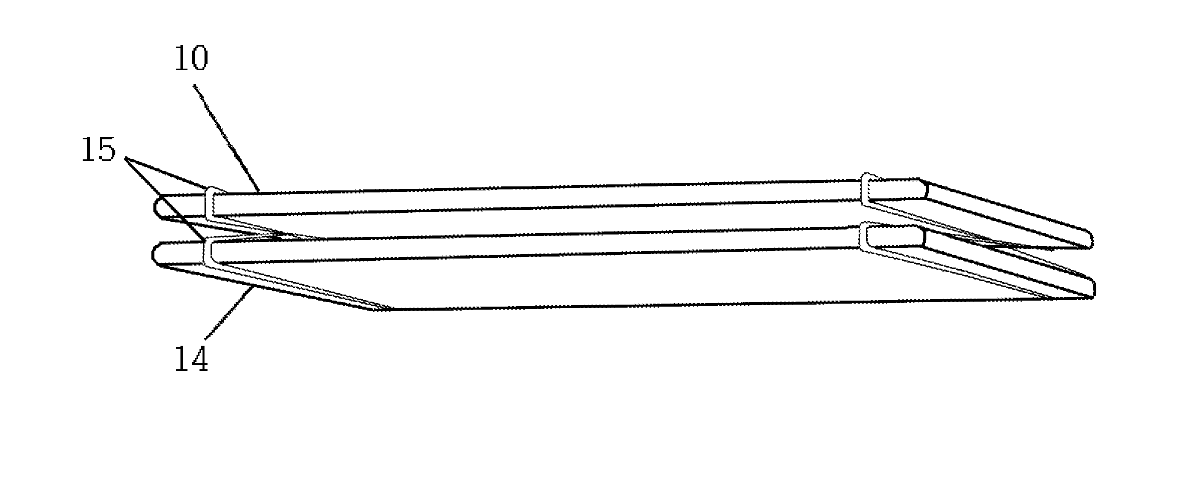
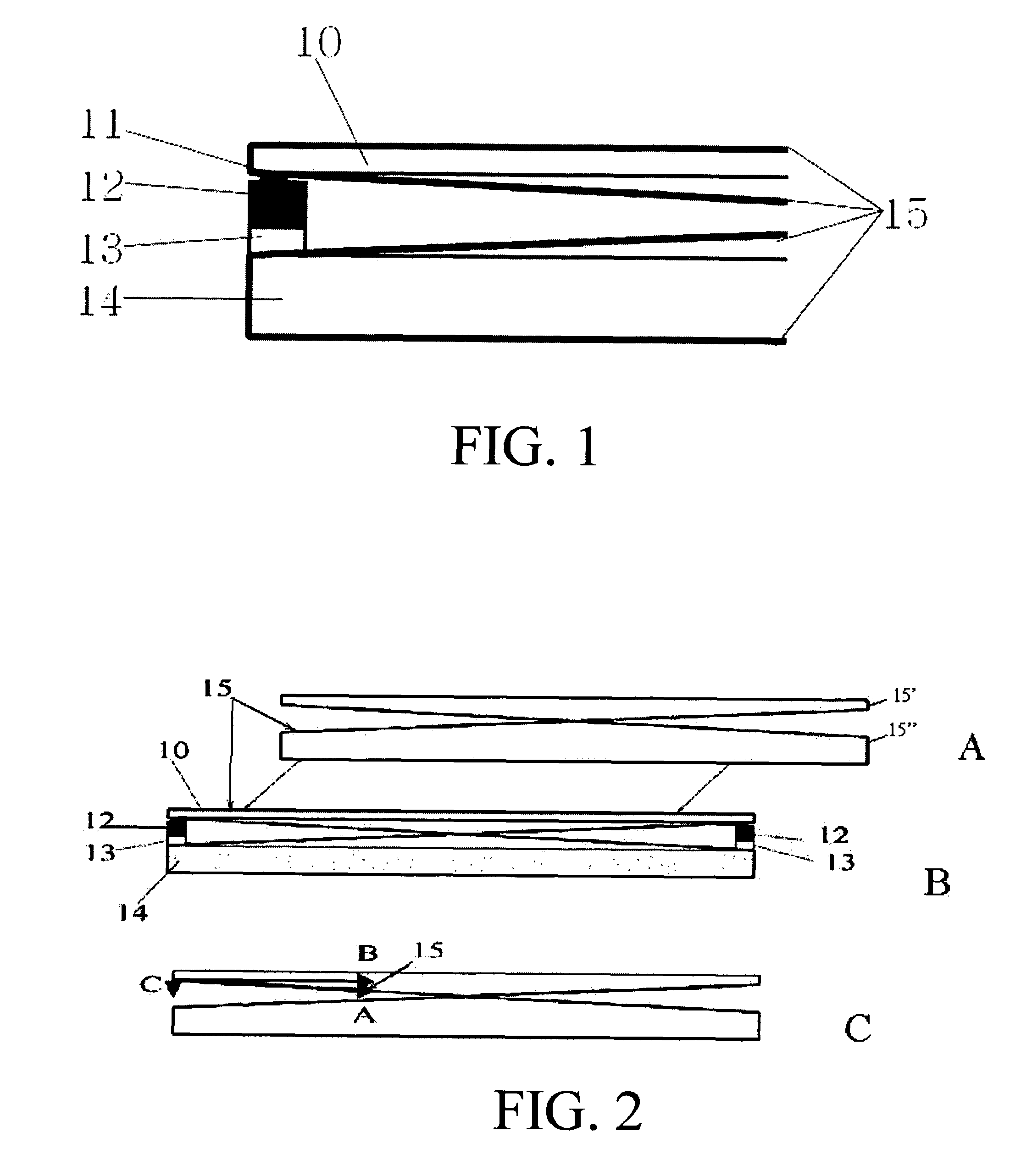
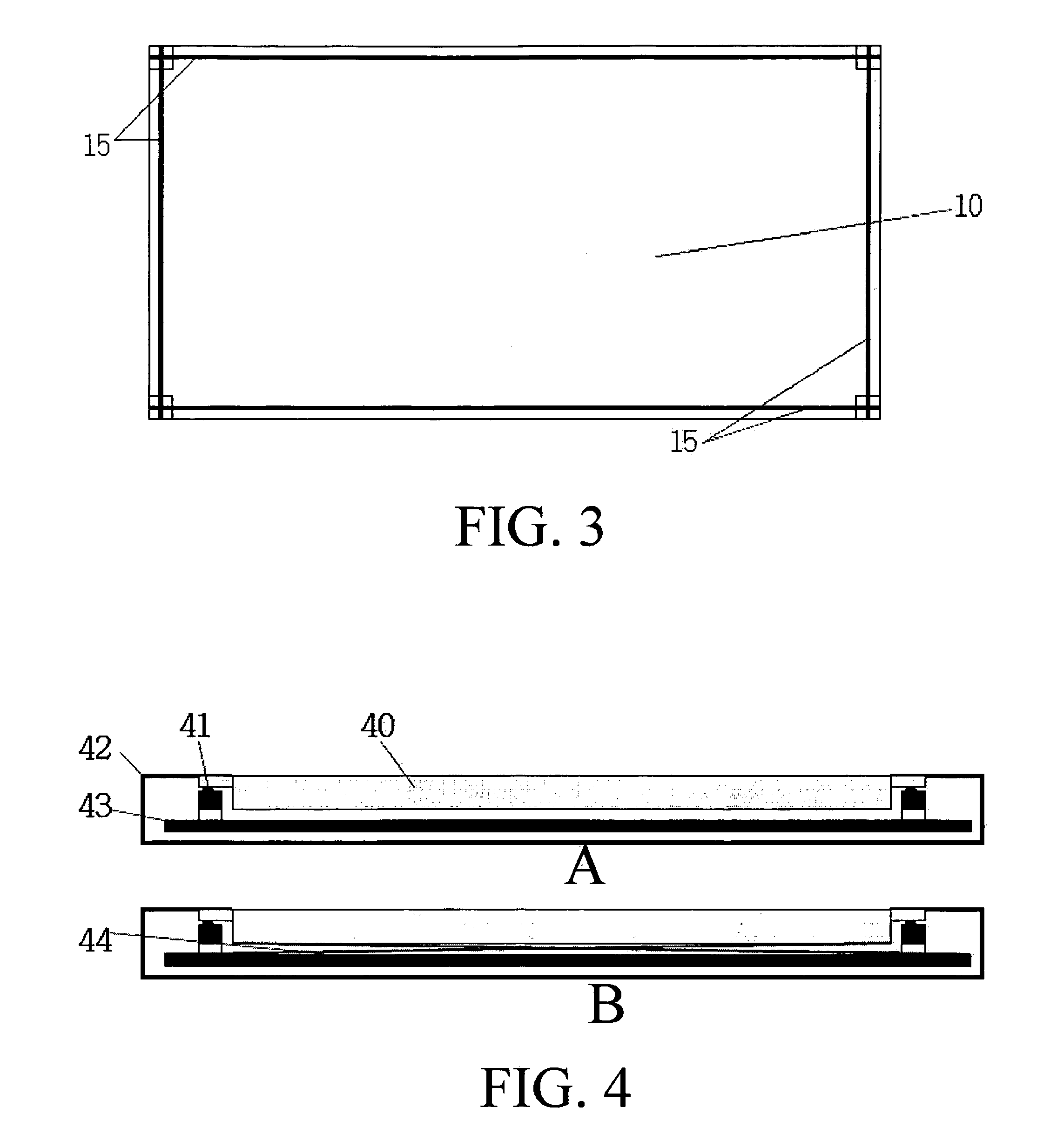
[0056]The present invention is a mechanical suspension for a touch screen display that does not add any additional non-linear forces to a touch screen system, and which preloads the touch screen sensor(s) to alleviate the need for extremely tight mechanical tolerances. The invention adapts a unique and different approach for mechanically connecting a touch screen lens to the force sensors, and to also provide a pre-loading force against the sensors with minimal non-linear changes over applied force pressure.

[0057]The illustrated embodiments of the present invention adhere to the following principles which are required for proper operation.[0058]The two opposing surfaces defined by the touch lens and sensor mounting plane, need to be flat and parallel.[0059]The touch lens needs to touch the sensors when at rest (non-touch mode), with or without pre-loading applied.[0060]The touch lens needs to be free to move down towards the bottom plate when a force is applied on the top of it.[006...


PUM


Abstract

A suspension system for a differential-pressure touch sensitive panel suspended over force sensors, for use in either fixed or mobile devices such as point of sales terminals, kiosks, laptops, monitors, PDAs, cell phones, UMPCs and more. In one embodiment, each side of the lens is encircled and supported by a looped string, monofilament or flexible wire, which is then looped around the back cover or base plate, forming a figure-8. The figure 8-loops bring the lens into a fixed state in the xy-plane without the addition of any friction causing physical contact. Other alternative implementations include continuous suspensions, bender suspensions and 3-dimensional force suspensions. Moreover, the present invention proposes the use of a flexible padding under the force sensors to allow the sensors to be slightly preloaded, which reduces the dependency on extremely tight mechanical tolerances.

Description

CROSS-REFERENCE TO RELATED APPLICATIONS[0001]This application is a National Stage of International Application No. PCT / US2008 / 003374, filed Mar. 14, 2008, which claims the benefit of U.S. Provisional Patent Application No. 60 / 918,275, filed Mar. 15, 2007, which is incorporated by reference in its entirety.BACKGROUND OF THE INVENTION[0002](1) Field of the Invention[0003]The present invention relates to mechanical touch input systems such as touch pads and touch screens used in fixed or mobile devices, such as point of sales terminals, kiosks, laptops, monitors, PDAs, cell phones, UMPCs and more, that require the touch component to be fully constrained in two directions (x & y), but requiring unencumbered freedom to translate in the third direction (z-direction).[0004](2) Description of Prior Art[0005]The concept of using multiple force sensing sensors to register, measure and triangulate the touched position of a touch screen has been a known concept for more then twenty years, howev...

Claims


Application Information

Patent Timeline
Patent Type & Authority Patents(United States)
IPC IPC(8): G06F1/16H05K7/00H05K5/00G06F3/041
CPCG06F3/0414G02F1/13338G02F1/133526G06F1/1656G06F3/04142
Inventor BROWN, DANIEL EDWARDBROWN, CALEB DANIELMOLNE, ANDERS L.
Owner APPLE INC
Why Eureka
Try Eureka