Magnetic field sensor

a magnetic field sensor and output technology, applied in speed/acceleration/shock measurement, instruments, surveying and navigation, etc., can solve the disadvantages of known magnetic field sensors, and achieve the effect of ensuring the accuracy of the output of magnetic field sensors

Active Publication Date: 2012-04-03
NXP BV
View PDF18 Cites 2 Cited by
  • Summary
  • Abstract
  • Description
  • Claims
  • Application Information

AI Technical Summary

Benefits of technology

[0011]The field detector detects a magnetic field. In response to a field detection result, an indication signal is outputted. This indication signal is for example converted into a graphical pointer signal or into a numerical display signal. To be able to use the magnetic field sensor for relatively many purposes, the environment detector has been added. This environment detector detects an environment of the magnetic field sensor. In response to a first environment detection result indicative for a detection of a first environment, a first result signal is outputted, and, in response to a second environment detection result indicative for a detection of a second environment different from the first environment, a second result signal is outputted. These result signals are supplied to the processor that, in response to the first result signal, performs a first process for the field detector and that, in response to the second result signal, performs a second process for the field detector. So, in response to a detection of a particular environment, the processor performs a particular process for the field detector. This allows the magnetic field sensor to be used in different subsequent environments and therefore for relatively many purposes (inside different cars, on (motor)bikes, by pedestrians on the street, by pedestrians in trains etc.), without compromising an accuracy of the magnetic field sensor output.
[0012]The magnetic field sensor according to the invention is further advantageous, inter alia, in that it is more independent and self-supporting. Compared to the known magnetic field sensor that has to receive its pre-calibration data from a plant, the magnetic field sensor according to the invention has got the capability to investigate its environment on its own.
[0034]The invention solves the problem, inter alia, to provide a magnetic field sensor that can be used for relatively many purposes. The magnetic field sensor according to the invention is further advantageous, inter alia, in that it is more independent and self-supporting.

Problems solved by technology

The known magnetic field sensor is disadvantageous, inter alia, owing to the fact that it is designed to be installed in a vehicle in a non-removable way.

Method used


Image

  • Magnetic field sensor
  • Magnetic field sensor
  • Magnetic field sensor

Examples


Embodiment Construction

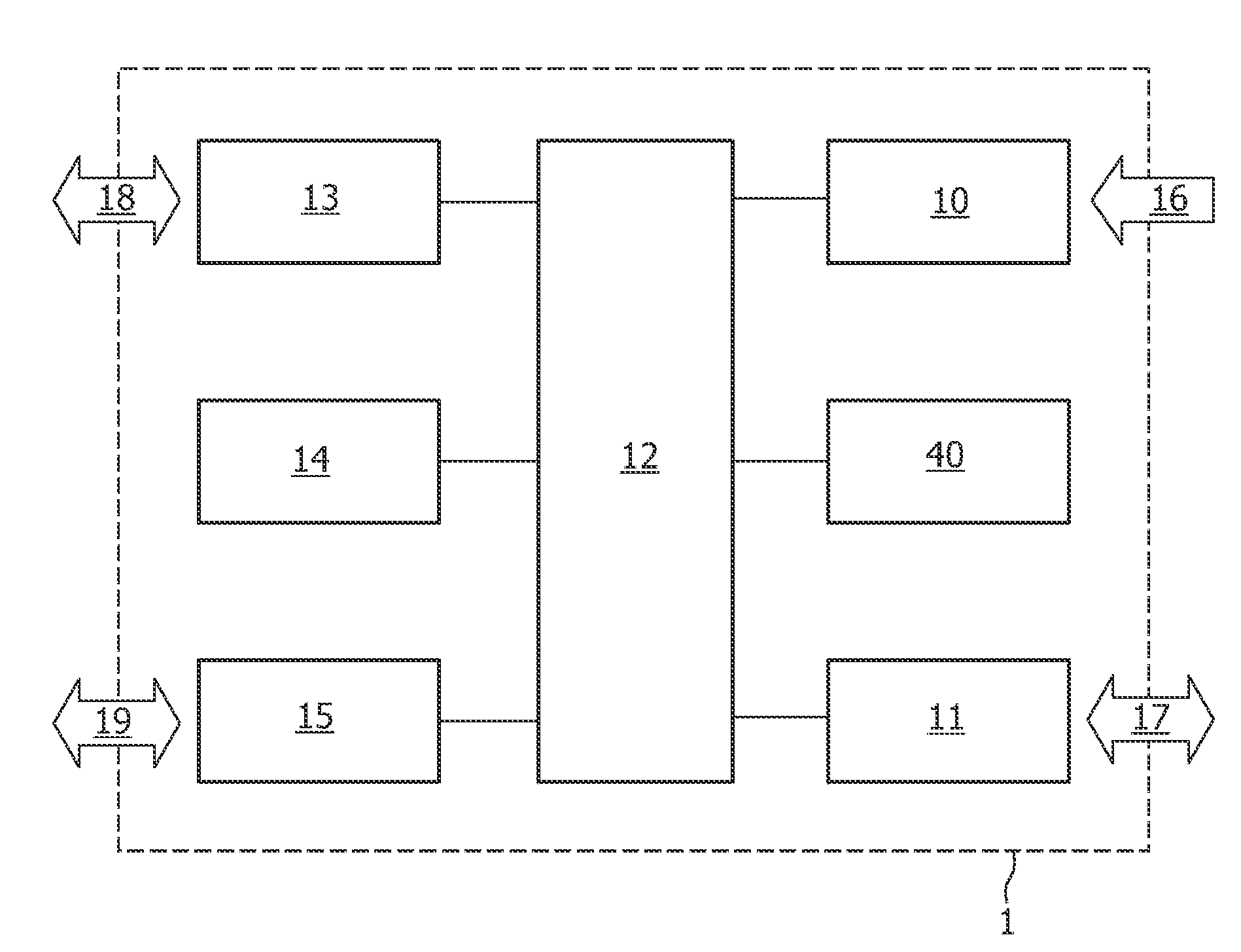
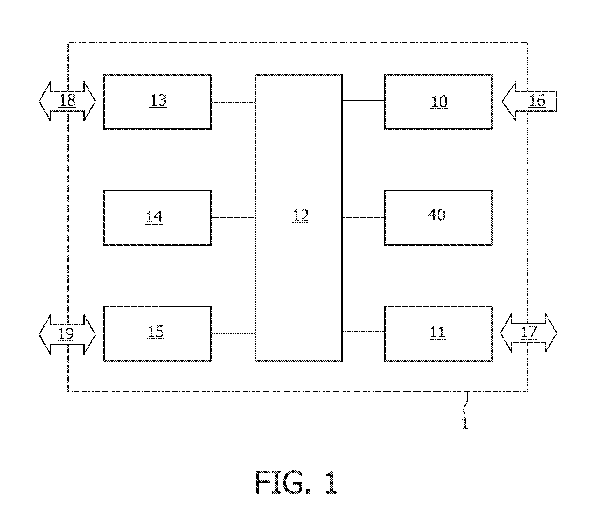
[0040]The magnetic field sensor 1 according to the invention shown in FIG. 1 comprises a field detector 10 for detecting a magnetic field and for, in response to a field detection result, outputting an indication signal. The magnetic field sensor 1 further comprises an environment detector 11 for detecting an environment and for, in response to a first environment detection result, outputting a first result signal and for, in response to a second environment detection result different from the first environment detection result, outputting a second result signal different from the first result signal. The magnetic field sensor 1 further comprises a processor 12 coupled to the field detector 10 and to the environment detector 11 for, in response to the first result signal, performing a first process for the field detector 10 and for, in response to the second result signal, performing a second process for the field detector 10, which second process is different from the first process...


PUM


Abstract

Magnetic field sensors (1) comprising field detectors (10) for detecting magnetic fields are provided with environment detectors (11) for detecting environments and with processors (12) for, in response to detected environments, performing processes such as loading calibration parameter sets and (re)calibrations for the field detectors (10), to allow the magnetic field sensors (1) to be used in different subsequent environments. The environment detectors (11) may comprise code detectors for detecting codes indicative for environments and may comprise user interfaces (13) for, in response to detected environments and via user interactions, selecting processes to be performed by the processors (12). Devices (2) comprise magnetic field sensors (1). Apparatuses (3) such as cradles removably fix the devices (2) and may comprise code generators (30) for generating the codes indicative for the environments.

Description

FIELD OF THE INVENTION[0001]The invention relates to a magnetic field sensor, and also relates to a device, to an apparatus, to a method for magnetic field sensing, to a computer program product and to a medium.[0002]Examples of such a magnetic field sensor are geomagnetic field sensors, and examples of such a device are compasses and mobile terminals comprising compasses.BACKGROUND OF THE INVENTION[0003]A prior art magnetic field sensor is known from U.S. Pat. No. 6,047,237, which discloses in general a compass pre-calibration method and more in particular a method of installing an electronic compass including mounting the electronic compass in a vehicle and downloading pre-calibration data into the electronic compass. This pre-calibration data may be selected corresponding to identified vehicle characteristics.[0004]The known magnetic field sensor is disadvantageous, inter alia, owing to the fact that it is designed to be installed in a vehicle in a non-removable way. The known ma...

Claims


Application Information

Patent Timeline
Patent Type & Authority Patents(United States)
IPC IPC(8): G01C17/38
CPCG01C17/00G01C17/38
Inventor IKKINK, TEUNISBOEVE, HANS
Owner NXP BV
Why Eureka
Try Eureka