
User input for an electronic device employing a touch-sensor

a touch-sensor and electronic device technology, applied in the field of data input devices, can solve the problems of increasing the number of keystrokes and time required for even simple entries, cumbersome electronic devices, slow or even unusable,

Inactive Publication Date: 2012-04-03
SONY CORP +1
View PDF10 Cites 125 Cited by
  • Summary
  • Abstract
  • Description
  • Claims
  • Application Information

AI Technical Summary

Benefits of technology

Enables rapid, accurate, and efficient alphanumeric input on compact devices by allowing single-handed operation and reducing the complexity of character selection, enhancing user experience and usability.

Problems solved by technology

As the space required for implementing the input interface becomes increasingly more limited, an improper design of this interface may render the electronic devices cumbersome, slow, or even unusable.
For example, too many buttons on the interface may disorient an unsophisticated user.
Too few keys may require that the available buttons be assigned secondary or even tertiary functions, greatly increasing the number of keystrokes and time required for even simple entries.
A cumbersome layout would render the data entry slow and tedious, while tiny keys or buttons would be difficult to see and manipulate and, in addition, would require extreme precision on the part of the user.
Additionally, the apparatus must interpret the handwriting into a computer readable format, and the procedure for doing so is time consuming and is also less than 100% accurate.
Furthermore, the variety of characters that may be entered may be limited based on the ability of the apparatus to discern between various handwritten material.
However, even these keyboards may be insufficient, since if the apparatus is small enough, the keyboard keys are so small so as to be difficult to use by the user.
Additionally, if the graphical display is too small, such a keyboard will not function properly.
The aforementioned interfaces, while functional, do not represent an optimal solution that adequately addresses the rapid input of alphanumeric and other data input in some electronic devices.
Accordingly, the need for such an input interface has heretofore remained unsatisfied.

Method used


Image

  • User input for an electronic device employing a touch-sensor
  • User input for an electronic device employing a touch-sensor
  • User input for an electronic device employing a touch-sensor

Examples


Embodiment Construction

[0041]The present invention provides a user input for electronic devices such as portable or hand-held electronic devices. Such devices include, without limitation, telephones, cellular phones, PDAs, game controllers, remote controls, keyboards, watches or even devices in which electronics can be embedded such as eyeglasses.

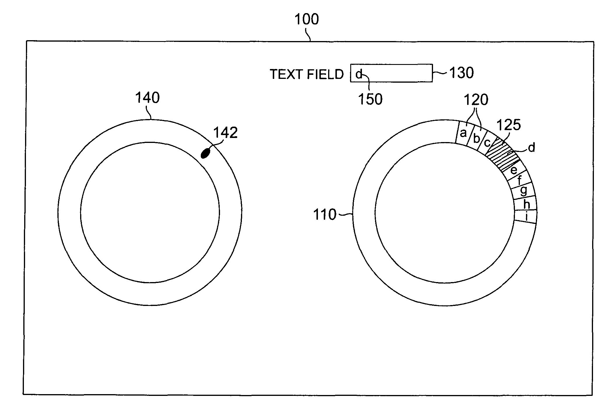
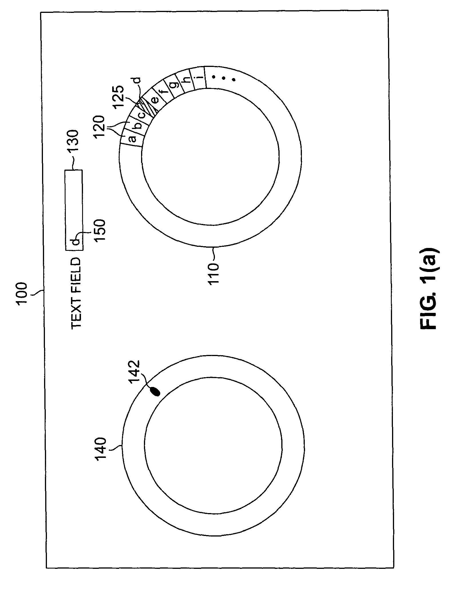
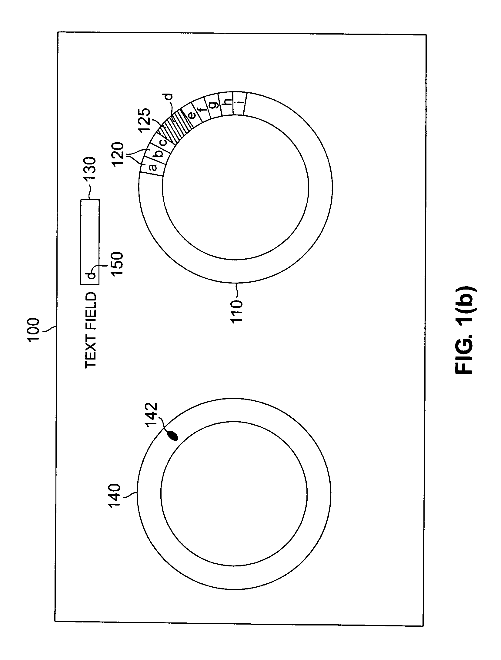
[0042]Referring first to FIG. 1(a), a graphical interface screen 100 constructed in accordance with the invention is depicted. Graphical interface screen 100 may be a CRT display screen, an LCD screen, or any other type of display screen. Currently, hand held electronic devices generally employ LCD screens. Within graphical interface screen 100 is displayed a graphical text entry ring 110 having a plurality of characters 120 positioned therein. A darkened or highlighted portion 125 of graphical text ring 110 depicts a selected character. The highlighted portion 125 may be distinguished from the unselected characters by a change in background or character color, f...


PUM


Abstract

A graphical text entry system for an electronic device is provided. The electronic device may be, for example, a portable or hand-held electronic device such as a cellular telephone, PDA, or the like. The system includes a graphical text entry screen and a graphical text entry ring displayed on the graphical text entry screen. A plurality of characters such as letters or numbers is positioned on the graphical text entry ring. The system also includes a touch sensor ring located on the graphical text entry screen for selecting individual characters from among the plurality of characters located on the text entry ring.

Description

FIELD OF INVENTION[0001]The present invention relates in general to the field of data input devices, and particularly to a character input interface for compact or hand held electronic devices requiring alpha-numeric inputs from the user.BACKGROUND OF INVENTION[0002]As electronic devices, such as personal digital assistants (PDAs), cellular phones and other hand held electronic devices continue to decrease in size, proper design of the input interface for these devices becomes more important. As the space required for implementing the input interface becomes increasingly more limited, an improper design of this interface may render the electronic devices cumbersome, slow, or even unusable. For example, too many buttons on the interface may disorient an unsophisticated user. Too few keys may require that the available buttons be assigned secondary or even tertiary functions, greatly increasing the number of keystrokes and time required for even simple entries. A cumbersome layout wou...

Claims


Application Information

Patent Timeline
Patent Type & Authority Patents(United States)
IPC IPC(8): G06F3/048G06F1/16G06F3/00G06F3/023G09G5/00
CPCG06F1/1613G06F1/169G06F3/0236G06F3/04886H04M2250/70
Inventor LAW, HO KEE HERBERTDONG, SHENGPRABHU, AMALKIKUCHI, TOSHIKI
Owner SONY CORP
Learn More