
Floor panel and method for manufacturing a floor panel

a technology of floor panels and floor panels, applied in the field of floor panels, can solve problems such as less satisfaction

Active Publication Date: 2012-04-10
FLOORING IND LTD
View PDF27 Cites 66 Cited by
  • Summary
  • Abstract
  • Description
  • Claims
  • Application Information

AI Technical Summary

Benefits of technology

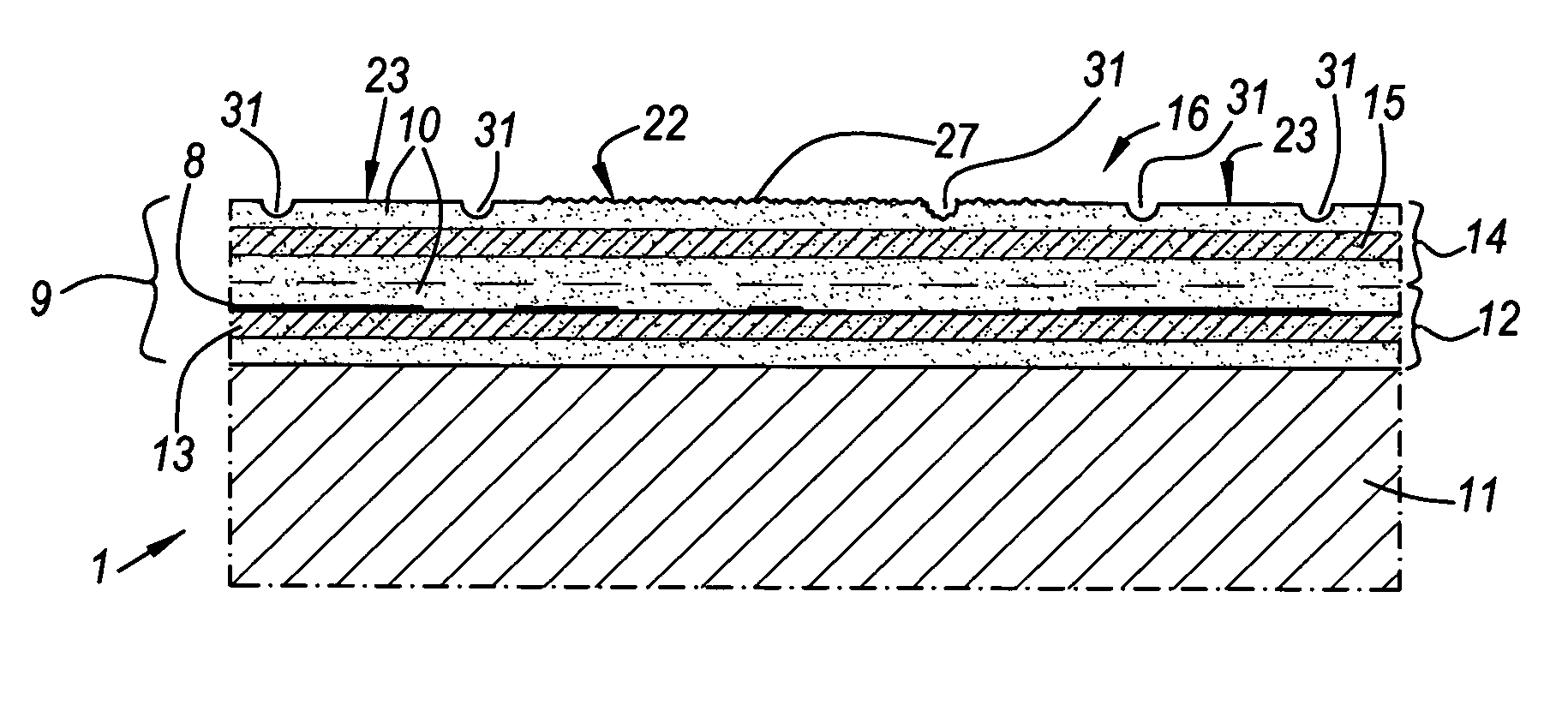
[0022]An advantage of providing the panel with a wood pattern that is formed by the gloss degrees, as well as of a wood pattern that is formed by colours, consists in that a person standing on a floor composed of such floor panels, almost always will observe a pattern, irrespective of the angle of the incident light. When this person is looking at panels in front of him, inclined against incident light, he will, due to the reflection of the light on the synthetic material surface, distinguish little or nothing of the pattern formed by the colours, but he will clearly distinguish the pattern created by the different gloss degrees. However, when looking straight or almost straight at the panels, and if there is only inclined incident light, he will hardly see the pattern formed by the gloss degrees, but will well distinguish the pattern formed by the different colour zones.
[0077]As explained above, an inkjet supply system can be automated in an easy manner, and employing such system, according to this third independent aspect, leads to a flexible and / or inexpensive method for manufacturing better finished floor panels, more particularly floor panels leading to less or no undesired visual effects in a floor covering.

Problems solved by technology

When imitating certain kinds of wood, in first instance dark and / or exotic kinds of wood, such as Wenge, the usual techniques are leading to less satisfying results.

Method used


Image

  • Floor panel and method for manufacturing a floor panel
  • Floor panel and method for manufacturing a floor panel
  • Floor panel and method for manufacturing a floor panel

Examples


Embodiment Construction

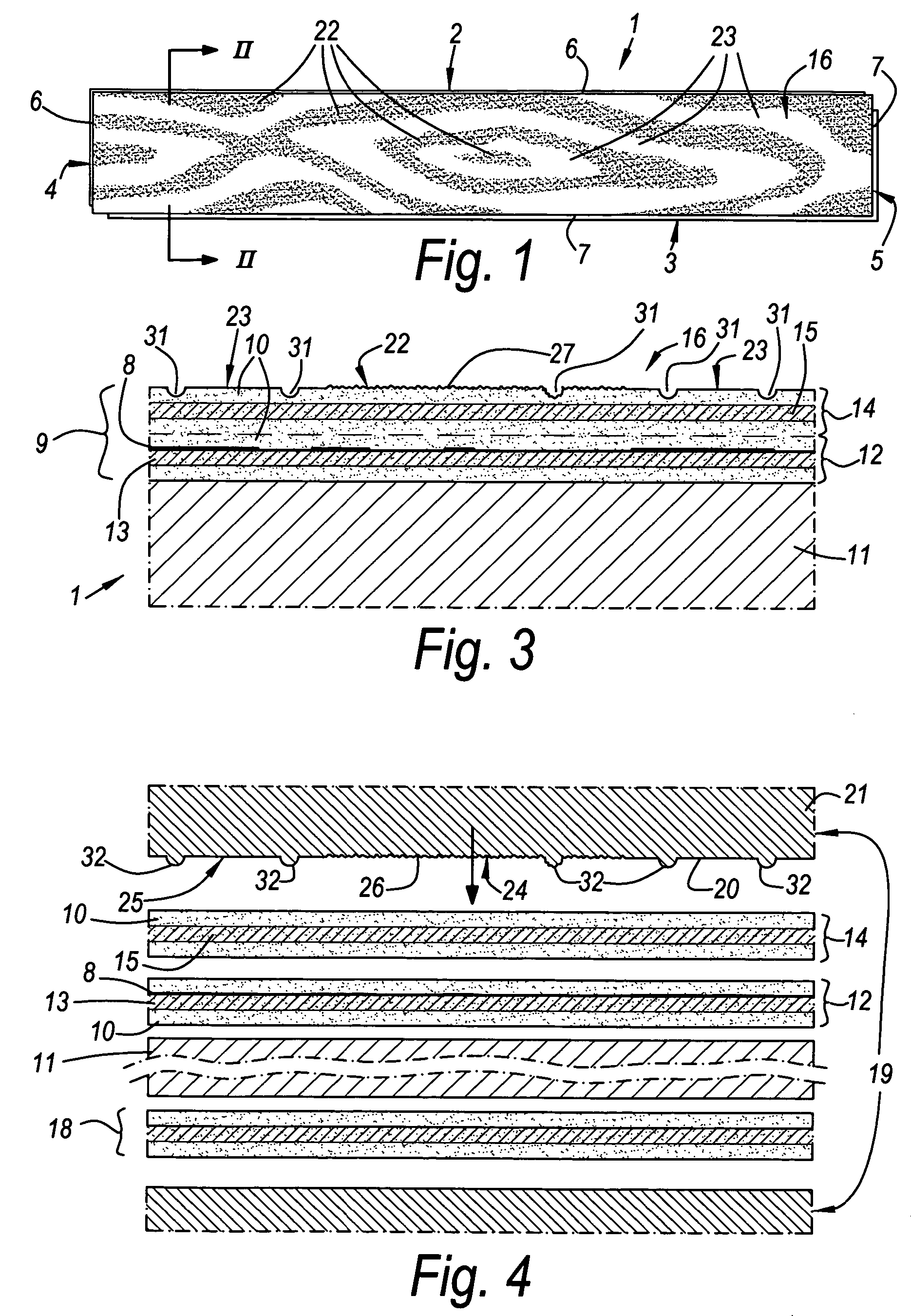
[0099]As represented in FIG. 1, the invention, amongst others according to its first aspect, relates to a floor panel 1 of the type intended for forming a floating floor covering.

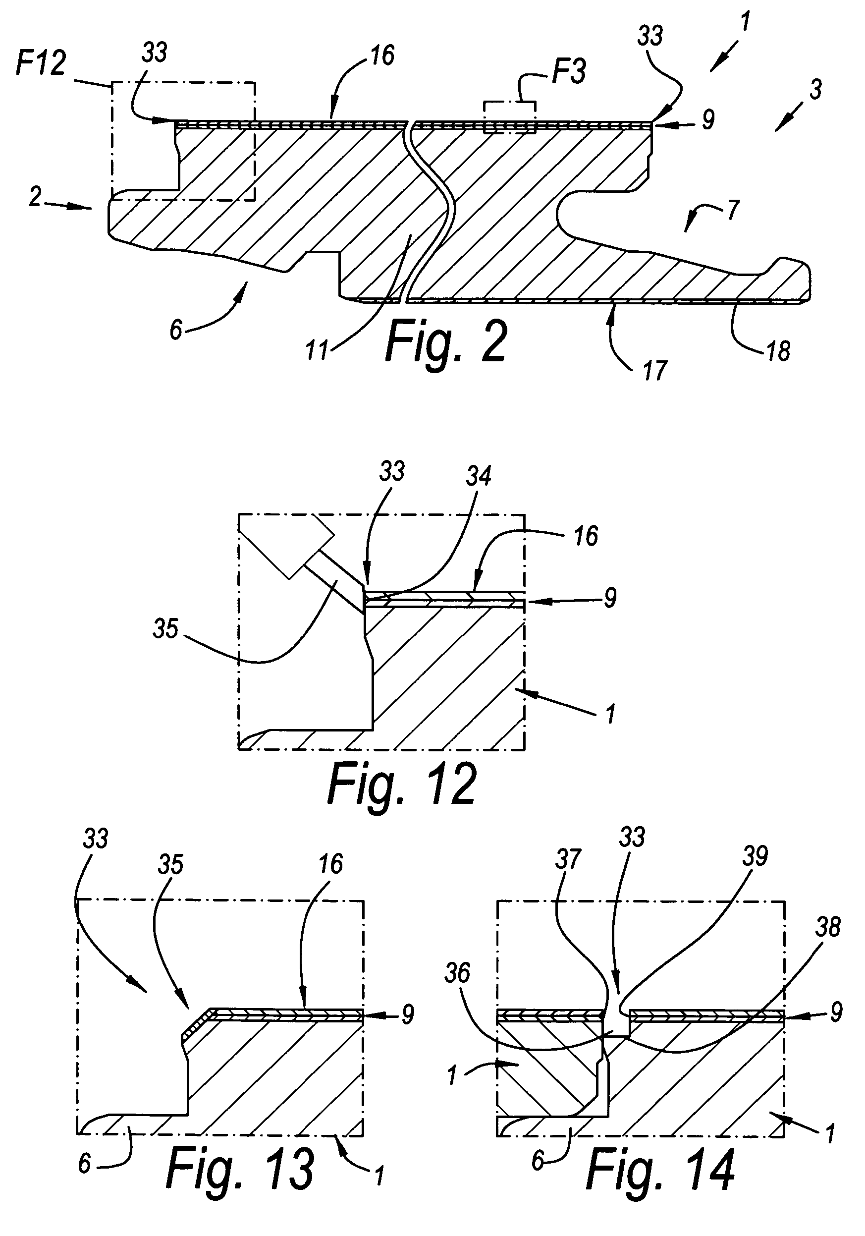
[0100]As represented in FIGS. 1 and 2, this floor panel 1 preferably, at least at two opposed edges 2-3, and preferably at both pairs of opposed edges 2-3 and 4-5, is provided with coupling parts 6-7, with which a plurality of such floor panels 1 can be coupled to each other. As represented, these coupling parts 6-7 preferably are of the type that, in coupled condition of the floor panels 1, effects a locking in vertical and horizontal directions. According to variants, other types of coupling parts, for example, coupling parts in the form of a normal tongue and groove, or coupling parts for realizing a so-called “drop-in” coupling, are not excluded. The coupling parts do not necessarily have to be manufactured in one piece with the body of the floor panel. Combinations of several types of coupling parts at...


PUM

PropertyMeasurementUnit
Raaaaaaaaaaa
thicknessaaaaaaaaaa
widthaaaaaaaaaa

Abstract

Floor panel, whereby this floor panel (1) includes a decor (8), as well as a top layer or laminate layer (9) on the basis of synthetic material (10), and whereby the decorative side (16) of the floor panel (1) imitates a wood pattern, wherein the floor panel (1), at its upper surface, has zones (22-23) of different gloss degrees, which extend over the upper surface as a function of the imitated global wood pattern.

Description

CROSS-REFERENCE TO RELATED APPLICATION[0001]This application claims the benefit under 35 U.S.C. 119(e) of Provisional Application No. 60 / 672,868 filed Apr. 20, 2005, the entirety of which is incorporated by reference in this application.BACKGROUND OF THE INVENTION[0002]A. Field[0003]This invention relates to a floor panel, more particularly a laminate floor panel, as well as a method for manufacturing a floor panel.[0004]B. Related Art[0005]In particular, it relates to a floor panel of the type intended for forming a floating floor covering, whereby this floor panel comprises a decor, preferably a printed decor, as well as a top layer based on synthetic material, and whereby the decorative side of the floor panel imitates a wood pattern.[0006]It is known that with laminate floor panels, often wooden floor parts or parquetry are imitated. It is known that the imitation mostly is performed by providing the floor panel with a printed decor representing a photographic image of wood.[000...

Claims


Application Information

Patent Timeline
Patent Type & Authority Patents(United States)
IPC IPC(8): D06N3/00E04C2/20B32B3/26
CPCB44B5/026B44C5/04B44F1/08B44F9/02E04F15/02E04F15/02033Y10T428/192Y10T428/24438Y10T428/19Y10T428/161Y10T428/24802Y10T428/24479Y10T428/24355E04F15/04
Inventor NOLLET, OKENAEYAERT, CHRISTOPHE
Owner FLOORING IND LTD
Learn More