Conductor wire connecting method, and connecting terminal, stator, and rotary electric machine

a technology of electrical conductor wire and connecting terminal, which is applied in the direction of cable junction, electric cable installation, and connection formation by deformation, etc., can solve the problems of insufficient squeezing of melted enamel coating, difficult to obtain necessary cross-sectional area, and insufficient electrical connection. , to achieve the effect of increasing the crimping degr

Active Publication Date: 2012-04-10
HITACHI ASTEMO LTD
View PDF7 Cites 2 Cited by
  • Summary
  • Abstract
  • Description
  • Claims
  • Application Information

AI Technical Summary

Benefits of technology

[0008]An object of the present invention is to provide the method of connecting plural electrical conductor wire of various electric appliances by the fusing system utilizing pressurization and electrification, and also to provide the method of ensuring electrical connection of the electrical conductor wire at the connecting terminals and enhancing mechanical tensile strength of the electrical conductor wire at the connecting terminals.
[0012]According to the present invention, the fusing system adopted for conductor wire connection makes it possible to increase the crimping degree of the conductor wire located in the end part of the above cross-section of the crimping connector in the shape of flattened tube formed so by pressure forming and to ensure electrical connection, while enhancement can be attained at the same time in the mechanical tensile strength of the conductor wire at the connector terminal.

Problems solved by technology

Therefore, in around the wire ends where the degree of crushing is little or less, it sometimes happens that the melted enamel coating cannot be squeezed out sufficiently, leaving the electrical connection in an incomplete state.
To the contrary, the electric conductor wire located in the center part used to be crushed to a more-than-necessary degree, leading to the problem that a necessary cross-sectional area was hard to obtain.
As mentioned above, the crushing degree of the electrical conductor wire ends to be crushed within the connector part is different depending on where the wire ends are located in the connector part during the fusing process, but none of the crushing conditions was enough to crush all the connecting wire ends in a stable state.
As a result, the enamel coating could not be squeezed out sufficiently from around the electrical conductor wire for which crushing was done only insufficiently, failing to complete electrical connection.
On the contrary, the crushing degree is higher in the center part than in both the end parts, causing such problem that the electrical conductor wire became short in mechanical tensile strength.

Method used


Image

  • Conductor wire connecting method, and connecting terminal, stator, and rotary electric machine
  • Conductor wire connecting method, and connecting terminal, stator, and rotary electric machine
  • Conductor wire connecting method, and connecting terminal, stator, and rotary electric machine

Examples


first embodiment

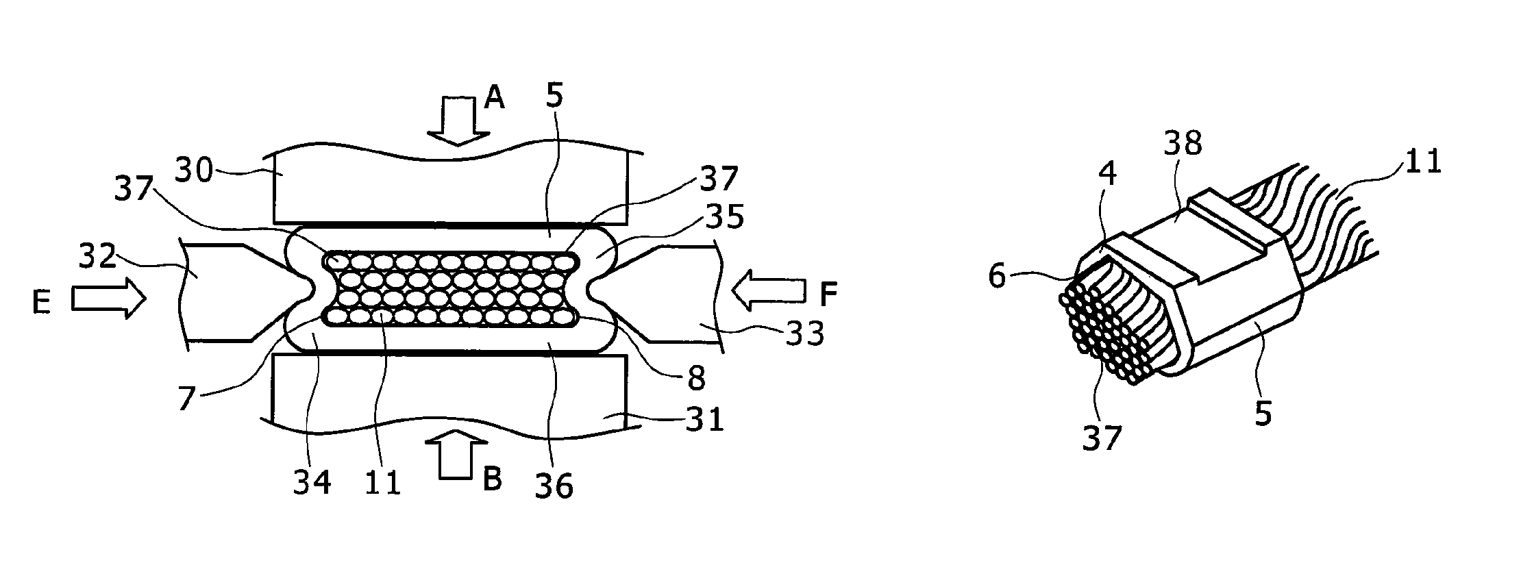
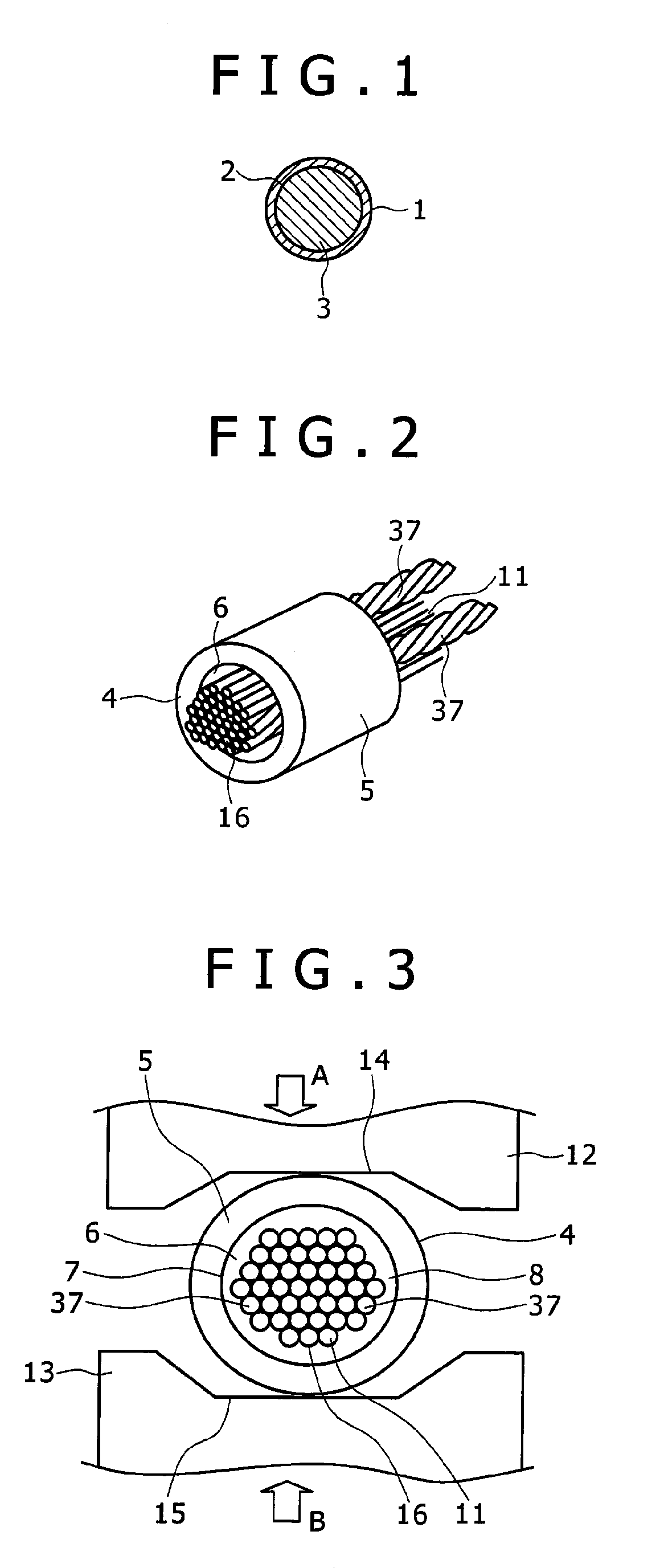
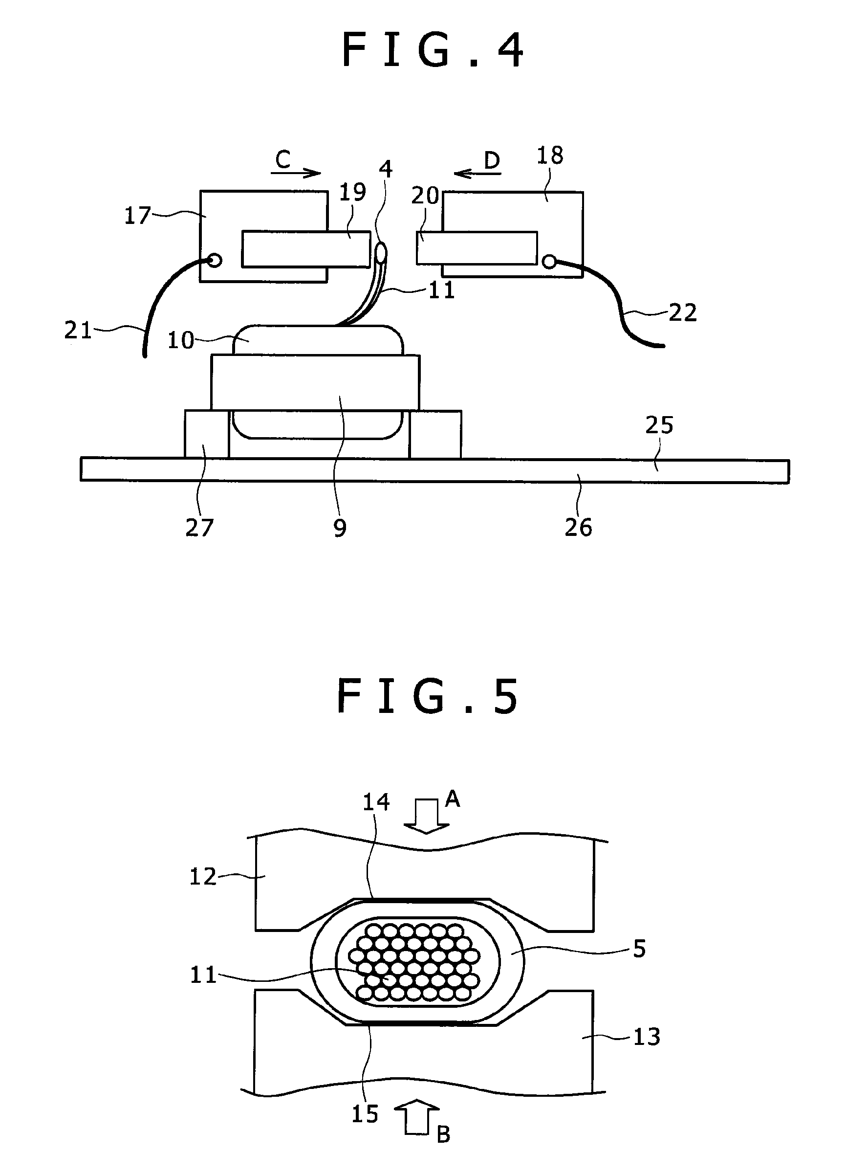
[0036]FIG. 1 is a cross-sectional view of the enamel-coated conductor wire as used in the present embodiment. FIG. 2 is a perspective view showing the state in which a bundle of conductor wires including twisted wire is inserted in a crimping connector, as used for the present embodiment. FIG. 3 is a schematic cross-sectional view showing the temporary crimping process as used in the present embodiment. FIG. 4 is a schematic side view of the fusing process (a heating and pressing device) as used in the present embodiment. FIG. 5 is a schematic cross-sectional view showing the state of the temporary crimping process in progress, as used in the present embodiment. FIG. 6 is a schematic cross-sectional view showing the state of the temporary crimping process after completed, as used in the present embodiment. FIG. 7 is a schematic vertical cross-sectional view showing the state of the fusing process following the completion of the temporary crimping process, as used in the present embo...


PUM

PropertyMeasurementUnit
shapeaaaaaaaaaa
timeaaaaaaaaaa
temperatureaaaaaaaaaa

Abstract

After melted enamel coating is discharged from the crimping connectors, electrical wire-to-wire connection, that is, the fusion process, is carried out inside the crimping connector. In this conductor connection method based on the fusion process, plural the above enamel-coated conductor wires are inserted in the above crimping connector prior to the start of the fusion process. Further, the temporary crimping process which provides the crimping connector a temporary crimping by mechanical pressurizing means is also a part of entire process. Addition of force at both the end parts or either one of them of the cross-section orthogonal to the axis of the above crimping connector may cause expansion, which needs to be suppressed with external fore. At the same time, the areas of cross-section corresponding to both the end parts or either of them mentioned above should preferably be held as small as possible. The above temporary crimping is applied to the above crimping connector for this purpose.

Description

FIELD OF THE INVENTION[0001]This invention relates to a connecting method of electrical conductor wire; and connecting terminals, stators, and rotary electric machines.BACKGROUND OF THE INVENTION[0002]Japanese Unexamined Patent Application Publication No. HEI11(1999)-40310 discloses the technique by which plural electric wires is electrically and physically connected to the terminals by inserting the electric wire ends in the terminals and fusing them all at the same time. Such an electrified caulking device as used for an electrical conductor wire connecting device of a fusing type comprises a pair of electrodes for heating and pressurization which are made movable so as to be able to vary the distance between the two electrodes, a driving means to move at least one of the two, and a power source capable of feeding electricity to both the electrodes. When the above electrical conductor wire connecting device is used for its intended purpose, a cylinder-shaped terminal inserted with...

Claims


Application Information

Patent Timeline
Patent Type & Authority Patents(United States)
IPC IPC(8): H01R4/18
CPCH01R4/20H01R43/05Y10T29/49201Y10T29/53235Y10T29/49179Y10T29/49185
Inventor MITA, TORUSAITO, YUJI
Owner HITACHI ASTEMO LTD
Why Eureka
Try Eureka