
Internal combustion engine having a cylinder crankcase and a V-shaped cylinder configuration

a technology of cylinder crankcase and configuration, which is applied in the direction of machines/engines, mechanical equipment, auxiliaries, etc., can solve the problems of installation space, and achieve the effect of replacing the cost of separate lubricant reservoirs and minimal addition costs in the casting of cylinder crankcases

Active Publication Date: 2012-04-17
AUDI AG
View PDF19 Cites 4 Cited by
  • Summary
  • Abstract
  • Description
  • Claims
  • Application Information

AI Technical Summary

Benefits of technology

The patent describes a lubricant reservoir for an internal combustion engine that is located within the cylinder crankcase. This eliminates the need for separate tubing and reduces installation space and costs. The lubricant reservoir is connected to a lubricant pump, which is also located within the reservoir. The reservoir has a removable cover that can be easily replaced for maintenance. The integration of the lubricant pump housing into the cylinder crankcase further reduces costs. Overall, this design provides improved efficiency and reliability for lubricating the internal combustion engine.

Problems solved by technology

But the disadvantage is that installation space for the configuration and the tubing of the separate lubricant reservoir must be provided in the engine compartment of the motor vehicle.

Method used


Image

  • Internal combustion engine having a cylinder crankcase and a V-shaped cylinder configuration
  • Internal combustion engine having a cylinder crankcase and a V-shaped cylinder configuration

Examples


Embodiment Construction

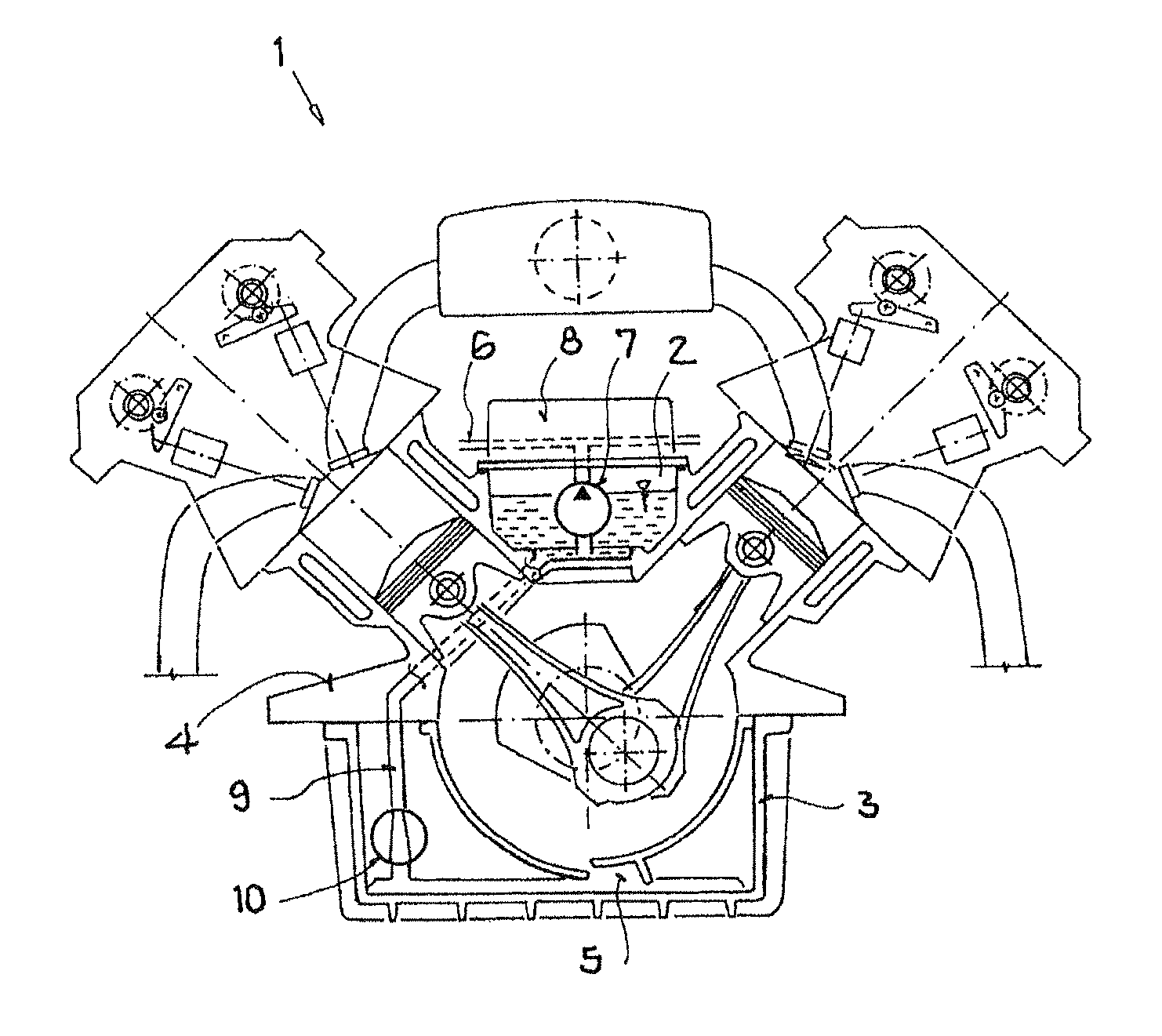
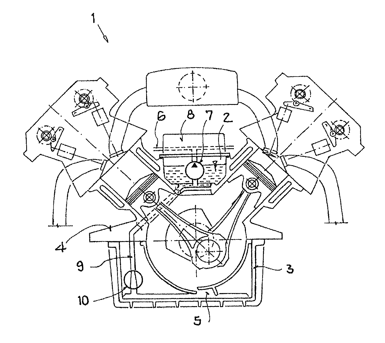
[0019]A v-shaped internal combustion engine that uses oil as the lubricant has a dry sump pressurized oil circuit whose oil reservoir is located between the two rows of cylinders, the oil reservoir being formed in one piece with the cylinder crankcase when the cylinder crankcase is cast.

[0020]The FIGURE shows a cross section through such an internal combustion engine 1. The pressurized oil circuit 6 which is only shown symbolically is driven by an external toothed gear oil pump 7 which is located within the oil reservoir 2 and which supplies all important lubrication sites of the internal combustion engine 1.

[0021]The oil reservoir 2 is filled by way of the dry sump return pump 10 which is located on the bottom of the crankshaft housing 3 for a small collecting space 5 which accommodates the oil which is flowing back from the lubrication sites. The connection between the dry sump return pump 10 and the external toothed gear oil pump 7 is formed by an oil line 9 which is preferably f...


PUM


Abstract

An internal combustion engine having a cylinder crankcase and a v-shaped cylinder configuration and having a lubricant circuit which operates according to the dry sump principle and has a lubricant reservoir, wherein the lubricant reservoir is located within the cylinder crankcase in the space between the cylinders.

Description

[0001]The invention relates to an internal combustion engine with a cylinder crankcase and a v-shaped cylinder configuration.BACKGROUND OF THE INVENTION[0002]Internal combustion engines with a lubricant circuit according to the dry sump principle have a separate lubricant reservoir into which the lubricant is pumped out of a small reservoir underneath the crankshaft by means of a lubricant pump, and out of which the lubricant is conveyed to the lubrication sites of the internal combustion engine. Such a lubricant circuit is described, for example, in document DE 38 20 480.[0003]One of the major advantages of dry sump lubrication consists in the lubricant reservoir which is not located underneath the crankshaft, as a result of which the internal combustion engine has a lower center of gravity and the internal combustion engine requires less installation space vertically.[0004]But the disadvantage is that installation space for the configuration and the tubing of the separate lubrican...

Claims


Application Information

Patent Timeline
Patent Type & Authority Patents(United States)
IPC IPC(8): F02B75/22F02F7/00F01M1/02
CPCF01M1/02F02B75/22F01M2001/126F01M2011/0083
Inventor STEMMER, XAVER
Owner AUDI AG
Learn More