Electrical screw terminal, block comprising one such electrical terminal and electrical apparatus comprising one such terminal block

a technology of electrical terminals and electrical screws, which is applied in the direction of electrical connections, clamped/spring connections, connections, etc., can solve the problems of a certain number of drawbacks of the type of telescopic screw, and achieve the effect of small dimensions and large clamping capacity

Active Publication Date: 2012-04-17
SCHNEIDER ELECTRIC IND SAS
View PDF13 Cites 5 Cited by
  • Summary
  • Abstract
  • Description
  • Claims
  • Application Information

AI Technical Summary

Benefits of technology

[0013]The object of the invention is therefore to remedy the drawbacks of the state of the art so as to propose a screw terminal having a large clamping capacity and having smaller dimensions.

Problems solved by technology

However, this type of telescopic screw presents a certain number of drawbacks.

Method used


Image

  • Electrical screw terminal, block comprising one such electrical terminal and electrical apparatus comprising one such terminal block
  • Electrical screw terminal, block comprising one such electrical terminal and electrical apparatus comprising one such terminal block
  • Electrical screw terminal, block comprising one such electrical terminal and electrical apparatus comprising one such terminal block

Examples


Embodiment Construction

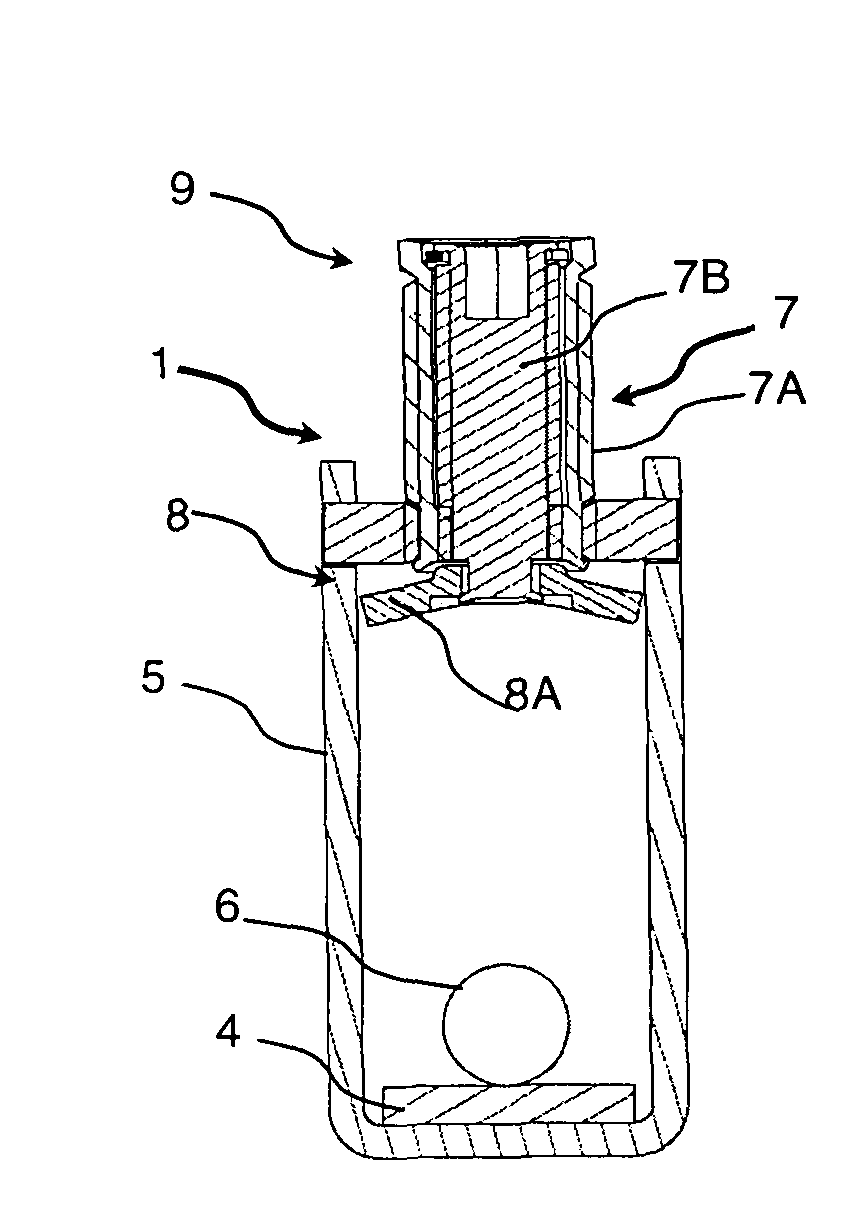
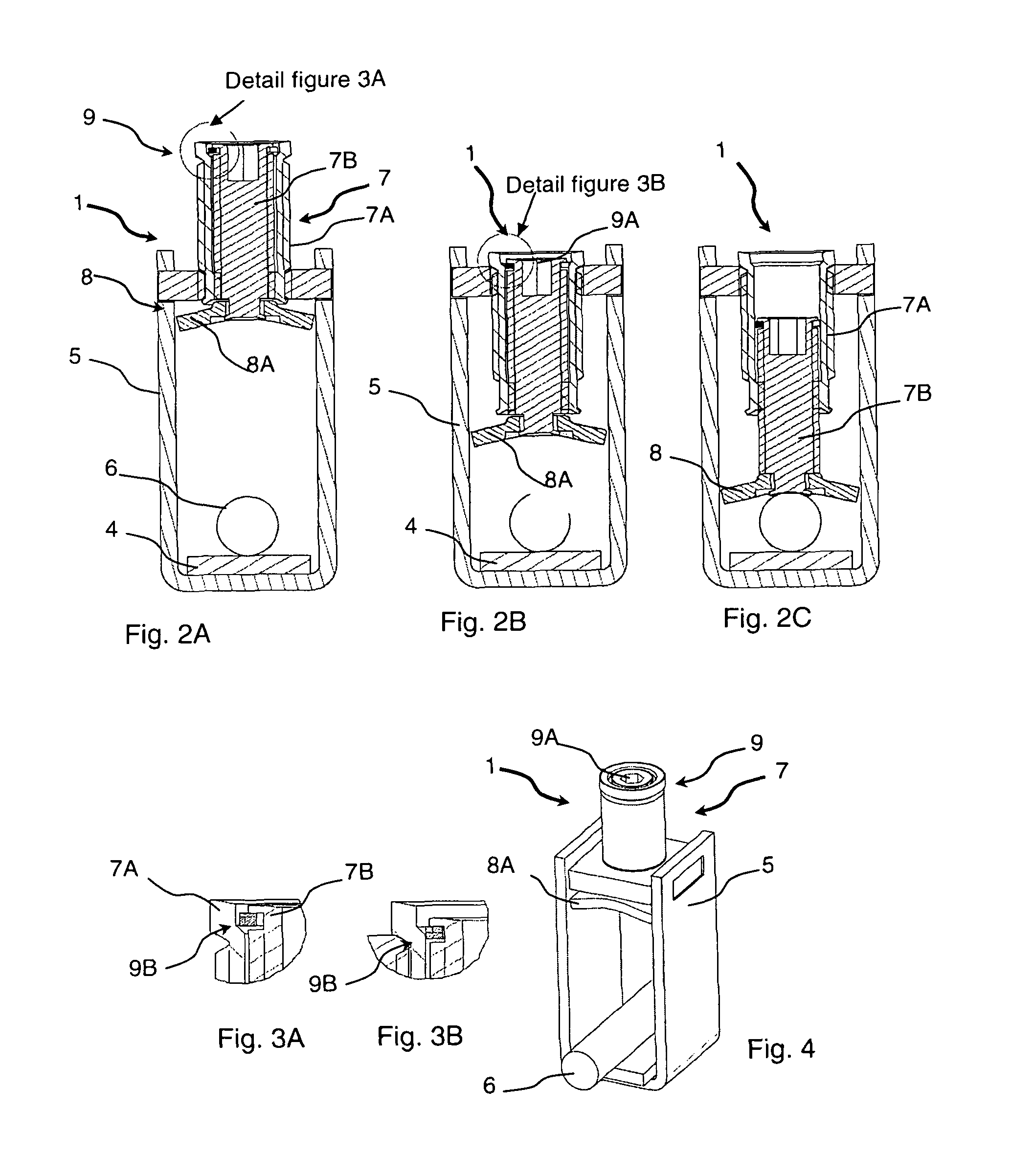
[0036]With reference to FIGS. 2A, 2B and 2C, according to a preferred embodiment, the electrical screw terminal 1 comprises a metal tunnel 5 through which an elongate passage runs designed to receive a connection strip 4 of an electrical apparatus. The electrical screw terminal 1 is in particular designed to connect electrical switchgear apparatuses, in particular circuit breakers, to electrical conductors.

[0037]The tunnel 5 comprises a tapped hole passing through a wall of said tunnel. As an example embodiment, the tunnel 5 is made from a flat metal part folded into a U. The two ends of the branches of the U are joined by a metal cross-member in which the tapped hole is made.

[0038]The electrical screw terminal 1 comprises a telescopic screw 7 designed to clamp an electrical conductor 6 and the connection strip. The telescopic screw 7 comprises at least a first cylindrical section 7A having an external thread designed to collaborate with the tapped hole. Said section also comprises ...


PUM


Abstract

An electrical screw terminal comprising a metal tunnel through which an elongate passage runs designed to receive a connection strip and comprising a tapped hole passing through a wall of said tunnel. The terminal comprises a telescopic screw passing through the tapped hole and comprising an operating head designed to be actuated to command said screw, a tightening head designed to clamp an electrical conductor and the connection strip. The telescopic screw comprises at least a first section having an external thread designed to collaborate with the tapped hole and having an internal thread designed to collaborate with an external thread of at least a second cylindrical section. The operating head comprises a single driving profile to drive said sections together in rotation via drive means.

Description

[0001]This application is a national stage entry of International Application No. PCT / FR2009 / 000587, filed May 18, 2009 designating the U.S., which claims the benefit of French Application No. 08 03646, filed Jun. 30, 2008.BACKGROUND OF THE INVENTION[0002]The invention relates to an electrical screw terminal comprising a metal tunnel through which an elongate passage runs designed to receive a connection strip of an electrical apparatus. The tunnel comprises a tapped hole passing through a wall of said tunnel. A telescopic screw passing through the tapped hole comprises an operating head designed to be actuated to command said screw and comprises a tightening head designed to clamp an electrical conductor and the connection strip. The telescopic screw comprises at least a first cylindrical section having an external thread designed to collaborate with the tapped hole and having an internal thread designed to collaborate with an external thread of at least a second cylindrical sectio...

Claims


Application Information

Patent Timeline
Patent Type & Authority Patents(United States)
IPC IPC(8): H01R4/36
CPCH01R4/307H01R4/36H01R9/24
Inventor TRICO, JEAN-MARIE
Owner SCHNEIDER ELECTRIC IND SAS
Why Eureka
Try Eureka