

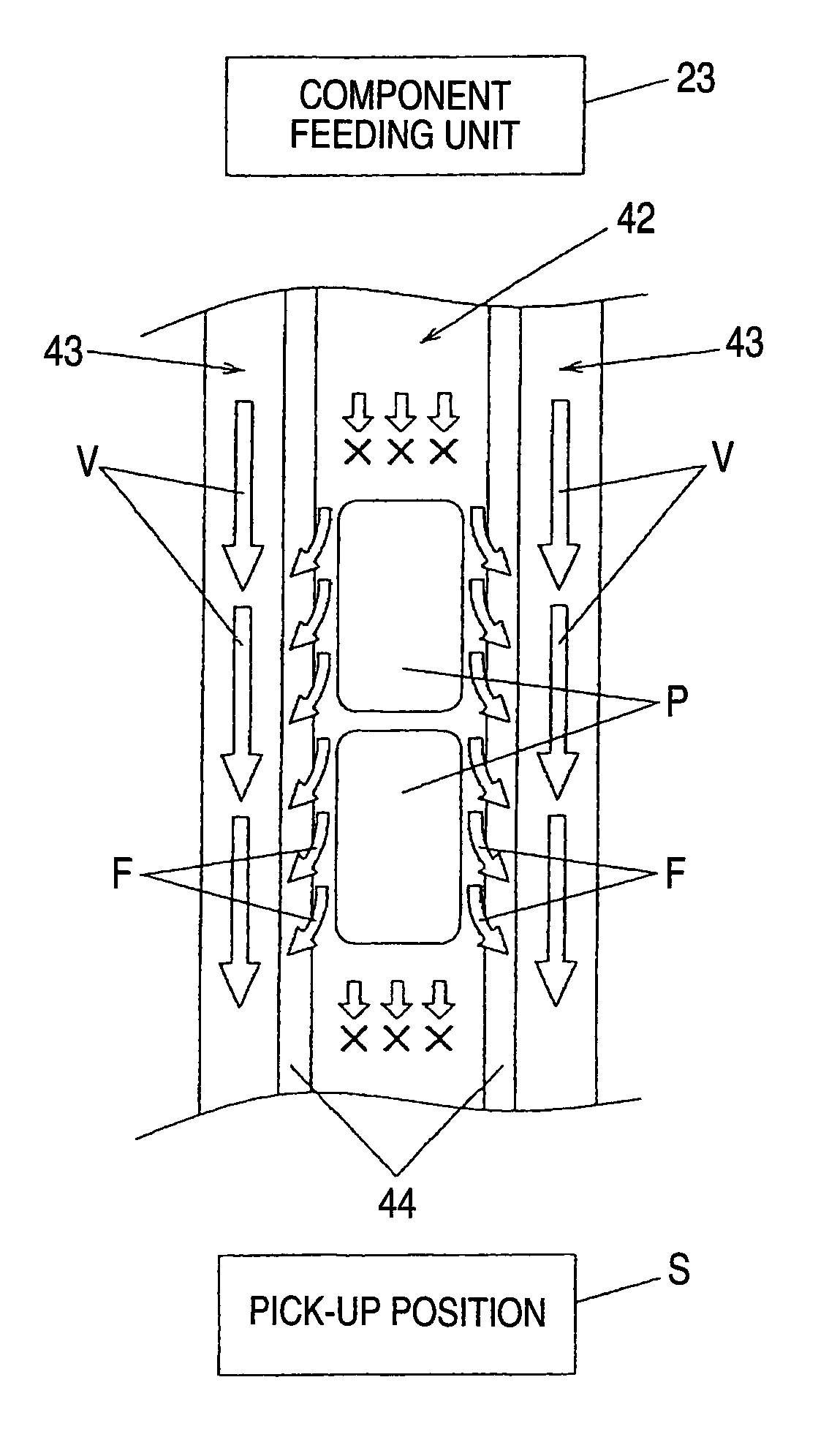
Bulk component feeder
a technology of component feeder and component, which is applied in mechanical conveyors, electrical equipment, loading/unloading, etc., can solve the problems of small airflow channel size and inability to ensure a desirable flow speed of airflow, and achieve the effect of not reducing the conveying speed of components and achieving the desired flow speed of air
- Summary
- Abstract
- Description
- Claims
- Application Information
AI Technical Summary
Benefits of technology
Problems solved by technology
Method used
Image

Examples
first embodiment
[0025]A first embodiment of the invention will be described with reference to the accompanying drawings.
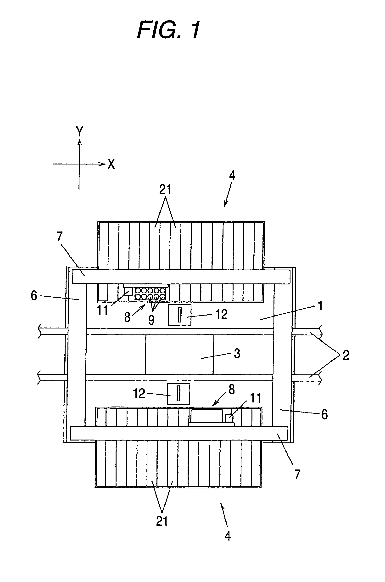
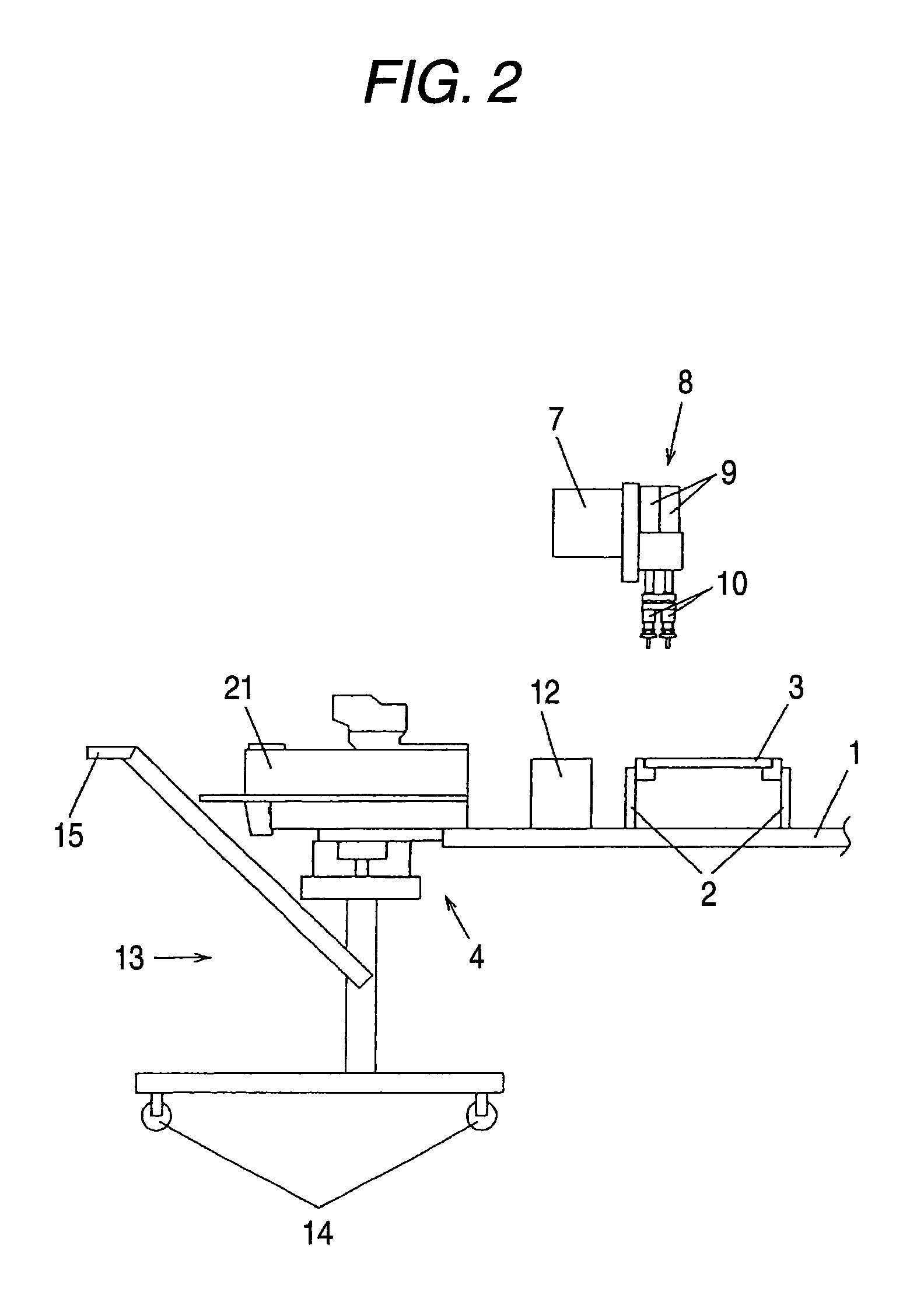
[0026]First, constituents of the mounting device of the electronic components will be described with reference to FIGS. 1 and 2. In FIG. 1, a conveying guide 2 is disposed on the center of a base 1. The conveying guide 2 acts as a substrate-positioning portion so that a substrate 3 as an object to be mounted is conveyed to be mounted on a predetermined position. In an aspect of the invention, a direction of conveying the substrate 3 is set as an X direction, and a direction that is perpendicular to the X direction on a horizontal plane is set as a Y direction.
[0027]Component feeding units 4 are disposed on both sides of the conveying guide 2 in the Y direction, and a plurality of bulk component feeders 21 are removably formed in parallel with one another. A pair of Y tables 6 are disposed at both ends of the base 1 so as to be perpendicular to the X direction. X tables 7 are built...
second embodiment
[0039]Next, a second embodiment of the invention will be described with reference to FIG. 7. Since the second embodiment is different from the first embodiment in terms of the shape of the guide, the shape of the guide will be described below.
[0040]In FIG. 7, a guide 50 is different from that of the first embodiment in that a ventilation channel 53 is formed only on one side of a conveying channel 52. The conveying channel 52 and the ventilation channel 53 are separated by a partition 54. A guide cover 51 is provided on the guide 50. The partition 54 is formed to be lower than a wall 50a of the guide 50, and a communication portion 55 through which the conveying channel 52 and the ventilation channel 53 communicate with each other is formed on the partition 54. An air groove 56 that is the same as an air groove 102 of the related art shown in FIG. 9 is formed at an upper portion of another side of the conveying channel 52.
[0041]In the guide 50, the ventilation channel 53, the commun...
third embodiment
[0042]Next, a third embodiment of the invention will be described with reference to FIG. 8. Since the third embodiment is different from the first embodiment in terms of shapes of the guide and the guide cover, the shapes of the guide and the guide cover will be described below.
[0043]In FIG. 8, a guide 60 and a guide cover 61 are different from those of the first embodiment in that a ventilation channel 63 is formed in the guide cover 61 instead of the guide 60. In the guide 60, a conveying channel 62 and an air groove 64 that are the same as the known guide 100 shown in FIG. 9 are formed. Two ventilation channels 63 are formed on a side of the guide cover 61 that faces the guide 60. The ventilation channels 63 communicate with the air groove 64 formed in the guide 60 while the guide cover 61 is provided on the guide 60. In connection with this, the air groove 64 forms a communication portion through which the conveying channel 62 communicates with the ventilation channels 63. A por...
PUM
 Abstract
Description
Claims
Application Information