
Processing apparatus, control method and storage medium

a processing apparatus and control method technology, applied in the field of processing apparatuses, can solve the problems of difficult to increase the memory capacity of slave units, the slave unit cannot store many error logs, and the performance of the master unit itsel

Inactive Publication Date: 2012-04-24
CANON KK
View PDF5 Cites 2 Cited by
  • Summary
  • Abstract
  • Description
  • Claims
  • Application Information

AI Technical Summary

Benefits of technology

The present invention provides a processing apparatus that can efficiently receive logs from external processing apparatuses without affecting the performance of the processing apparatus itself. The processing apparatus has a receiving unit to receive the logs, a calculation unit to calculate the priority of each external processing apparatus based on the operating situation of each apparatus, and a determination unit to decide whether or not to store the second log based on the priority. This allows the processing apparatus to efficiently collect and utilize the logs from external sources.

Problems solved by technology

Therefore, the slave unit cannot store many error logs.
However, if the master unit unconditionally accepts large logs in size such as error logs from a plurality of slave units, the performance of the master unit itself may degrade.
In order to address the problem, increasing the memory capacity of the slave units is difficult because of cost.
Therefore, priorities cannot be set dynamically depending on the operating situations of the slave units.
Further, in the situation in which the master unit itself has to perform various functions without degrading its performance, whether or not a log should be accepted cannot be determined dynamically depending on the condition of the master unit itself.
As just described, with the prior art, sufficiently efficient error log collection has not yet been realized.

Method used


Image

  • Processing apparatus, control method and storage medium
  • Processing apparatus, control method and storage medium
  • Processing apparatus, control method and storage medium

Examples


first embodiment

[0040][First Embodiment]

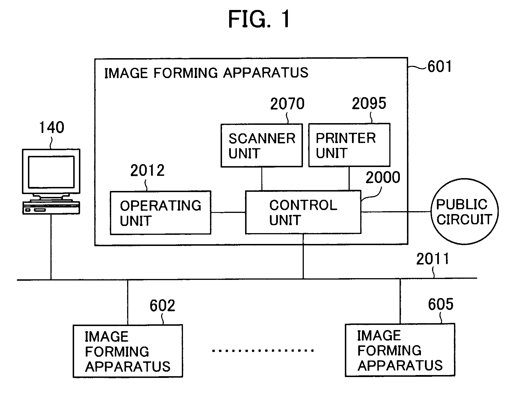
[0041]FIG. 1 is a block diagram showing the entire configuration of an image forming system including a processing apparatus according to an embodiment of the present invention.

[0042]The image forming system has an image forming apparatus 601 connected to a LAN 2011. The image forming apparatus 601 is an example of a processing apparatus. The image forming apparatus 601 includes a scanner unit 2070 which is an image input device, a printer unit 2095 which is an image output device, a control unit 2000 and an operating unit 2012 which is a user interface.

[0043]The scanner unit 2070, the printer unit 2095 and the operating unit 2012 are connected to the control unit 2000, respectively. In this case, the control unit 2000 is connected to the LAN 2011 (network) and a public circuit. The image forming apparatus 601 can receive and send data, including color images, through the public circuit using G3 and G4 facsimile functions.

[0044]In addition to other image form...

second embodiment

[0183][Second Embodiment]

[0184]In the first embodiment, when the storage of an error log is postponed, the master unit 601 instructs the slave units 602 to 605 to retransmit their error log storage request. In contrast, in the second embodiment, when the storage of an error logs is postponed, the master unit 601 obtains the error log from the slave unit 602 to 605 when it is convenient for the master unit 601. The second embodiment will now be described.

[0185]

[0186]An action taken when the master unit 601 postponed an error log storage request will be described with reference to FIG. 14. FIG. 14 is a conceptual diagram showing an action taken when the storage of an error log was postponed, wherein like numerals are assigned to the like elements in FIG. 5.

[0187]It is assumed that although the slave unit 604 sent an error log storage request 1602, the master unit 601 rejected the error log storage request 1602. At this moment, the master unit 601 adds the slave unit 604 to an error lo...

third embodiment

[0207][Third Embodiment]

[0208]A third embodiment is similar to the second embodiment on the point that when an error log storage has been postponed, the master unit 601 stores the error log of the slave unit when it is convenient for the master unit 601; however, the method for storing is different from that of the second embodiment.

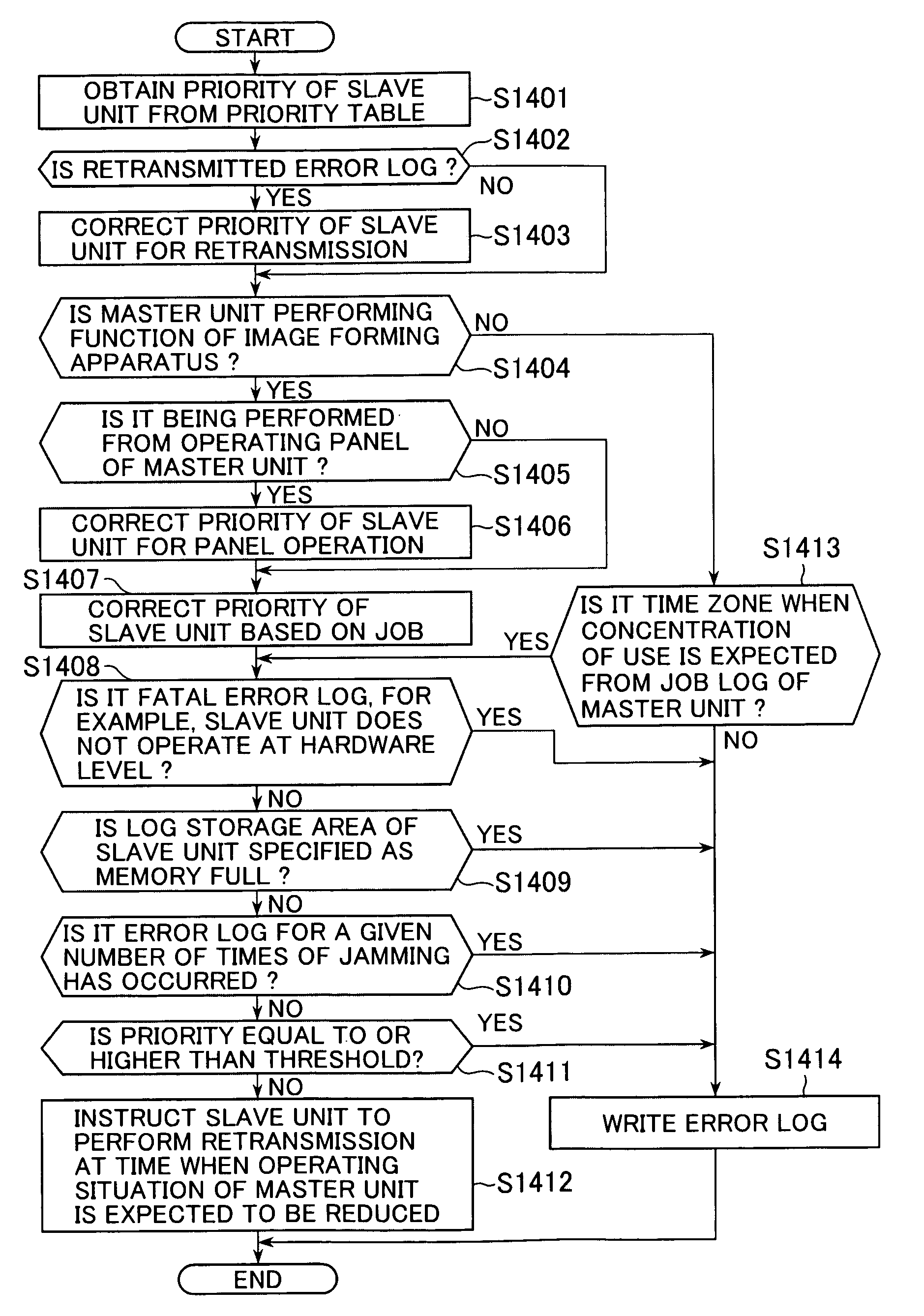
[0209]In the third embodiment, when the master unit 601 itself is not performing the function of the image forming apparatus and also it is not the time zone when the concentration of the use is expected from the job log 610 of the master unit 601 itself, the priorities of the slave units in the storage waiting list are corrected. Then, the master unit 601 obtains the error log of the slave unit having the highest corrected priority.

[0210]

[0211]A method of correcting priorities will now be described.

[0212]For example, the correction value “γ” related to the number “n” of error log storage requests is determined:

γ=15×n

[0213]According to FIG. 16, the corr...


PUM


Abstract

A processing apparatus that can accept logs from external processing apparatuses efficiently without degrading the performance of its own. The processing apparatus is connected with a plurality of external processing apparatuses for sending a first log including information on frequency of usage and a second log including information on an error, and collects the first and second logs from the external processing apparatuses. A receiving unit receives the first log sent from each of the external processing apparatuses. A calculation unit calculates a priority of each the external processing apparatuses based on the operating situation of each of the external processing apparatuses determined from the first log received by the receiving unit. A determination unit determines whether or not the second log sent by each of the external processing apparatuses should be stored based on the priority calculated by the calculation unit.

Description

BACKGROUND OF THE INVENTION[0001]1. Field of the Invention[0002]The present invention relates to a processing apparatus such as a copying machine having a function of collecting logs, a control method of the processing apparatus, and a storage medium storing therein a control program for executing the control method.[0003]2. Description of the Related Art[0004]An environment where a dedicated server is not placed and an image forming apparatus is used as a server so that a network can be operated without a dedicated server is becoming increasingly widespread in offices. In such a situation, an image forming apparatus (a master unit) having higher performance, for example, having a high-speed CPU or a high-capacity memory, has a server function, including a device management function of managing a plurality of image forming apparatus (slave units) on a network.[0005]In such a device management for slave units by a master unit, logs are collected from the slave units. Logs include nor...

Claims


Application Information

Patent Timeline
Patent Type & Authority Patents(United States)
IPC IPC(8): G03G15/00G06F11/34
CPCG06F11/3476
Inventor MIZUNO, TAKAFUMI
Owner CANON KK
Learn More