Split ring and pellet method stitchless fastener coil separation tool

a technology of separating tools and ring coils, which is applied in the direction of manufacturing tools, keys, travelling objects, etc., can solve the problems of inconvenient bag handling, inability to disclose the anti-rotational properties of the tool tips, and inability to accurately position the tool tips where necessary prior to insertion between the coils. to achieve the effect of efficient bag handling and convenient bag handling

Inactive Publication Date: 2006-04-18
MENTKEN ROBERT
View PDF6 Cites 4 Cited by
  • Summary
  • Abstract
  • Description
  • Claims
  • Application Information

AI Technical Summary

Benefits of technology

[0029]remain in position to efficiently accept the next assembly cycle.
[0030]A split ring is placed into and held stationary in the holding compartment at the center of a flat plate. A pair of L-shaped prying tools with round shafts and screw driver-like tips are controlled by a pair of guidance channels which point their prying tips at the parting groove defined by the top and bottom coils of the split ring. A spring strip attached to the flat plate keeps each tool snugly within its guidance channel and its tip aligned with the parting groove by pressing against a flat portion of the tool shafts. The prying tools are free to slide a limited distance along their guidance channels and rotate around their own axis. Their handles overhang the flat plate at each end. The operator pushes on the backs of both handles simultaneously, sending the tool tips between the coils, parting them slightly. The tool tips are prevented from traveling too far into the split ring's interior by either of two alternative stopping means: The first is a collar affixed to the tool shaft which fits partway into a box-shaped widened portion of the guidance channels whose front and rear walls limit the tools' travel in both directions along the guidance channels. The other stopping means is a rivet or pin affixed to the flat portion of the tool tips at a predetermined distance from the tip ends. The rivet or pins' contact with the coils prevents the tips from entering too far into the split ring's interior. In the other direction, the rivet or pins' contact with the spring strips stops the tools. Utilizing the leverage of the L-shaped handles to overcome the power of the coils, the operator rotates them 90-degrees, simultaneously, in opposite clock directions thereby separating the coils a distance equal to the width of the tool tips. The operator now places a bag corner bump between the separated coils and into a portion of the split ring interior unoccupied by the tips. The operator then reverses the handle rotation, which partially closes the coils around the bag corner bump, then pulls the prying tools out from between the coils, away from the holding compartment, which allows the coils to close completely, thereby capturing the bag corner bumps. Now the bag corner and its attached split ring can be lifted out of the clip holding compartment as a unit. Cantilevered suspension of the coil-spreading tool above a work surface with a bracket facilitates bag handling in production.

Problems solved by technology

Furthermore, nothing in the applicant's issued patent discloses what anti-rotational stabilizing force opposes the operators ¼ turn rotating action after the tool tips have been inserted between the coils.
Since there is nothing to guide the tool tips into its correct position, the time that it takes an operator to position the tool tips exactly where necessary prior to insertion between the coils is relatively lengthy because the operator must hunt for the correct position each time.
Lack of guidance of the tool tips towards their destination between the coils contributes immensely to undesirably long production cycle times.
There is also nothing to guide the bag corner bumps on its way into its correct position between the coils.
The time that it takes an operator to position the bag corner exactly where necessary prior to insertion between the coils is relatively lengthy because the operator must hunt for the correct position each time.
Lack of such guidance also means undesirably long production cycle times.
Using two unguided prying tools, uneven and asymmetrical tool tip insertion causes the separation distance between the opposing coils to be non-uniform across the width of the split ring, which interferes with ease of insertion of the bag corner bump.
Due to the tremendous force of their coils, without positively controlling them at the time of prying them apart, the split rings are unstable and dangerous.
They can easily and suddenly snap out of position, go flying violently and cause operator injury, or at the least, damage the bag material;

Method used


Image

  • Split ring and pellet method stitchless fastener coil separation tool
  • Split ring and pellet method stitchless fastener coil separation tool
  • Split ring and pellet method stitchless fastener coil separation tool

Examples


Embodiment Construction

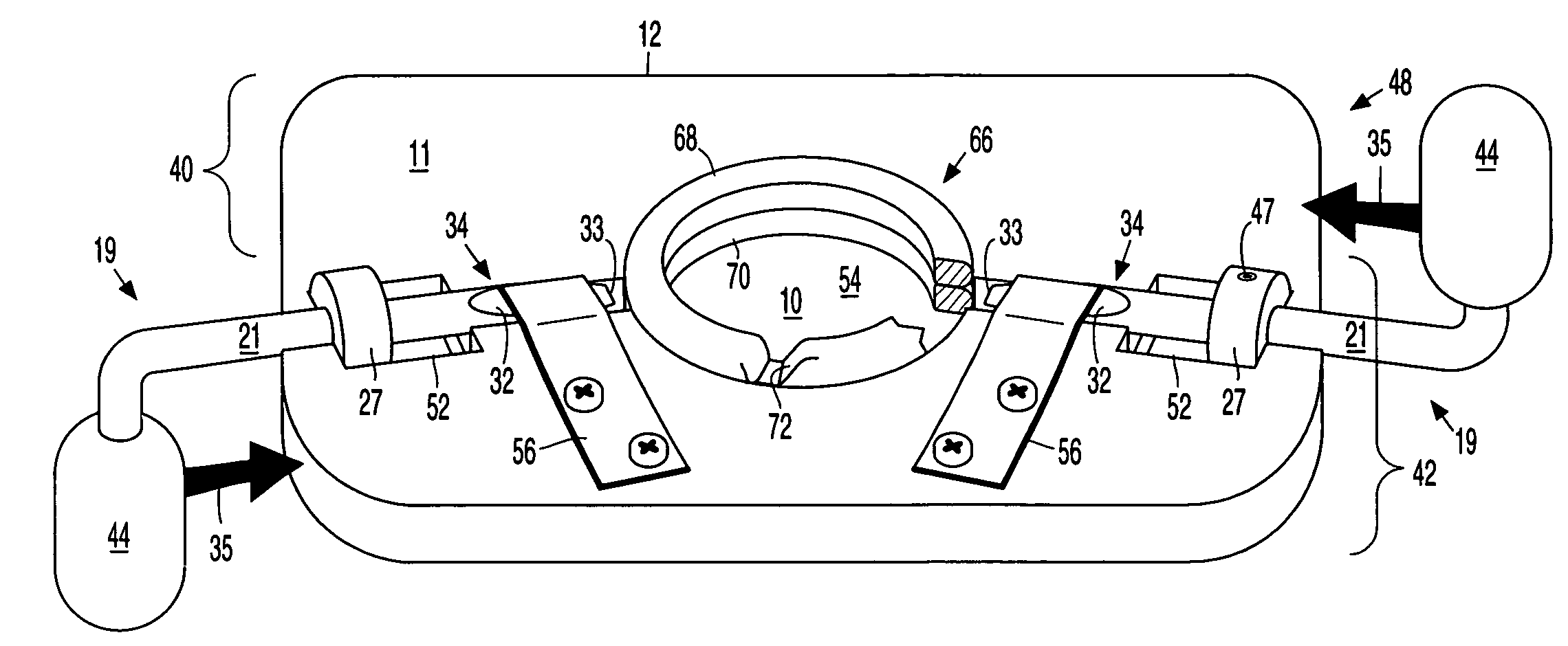
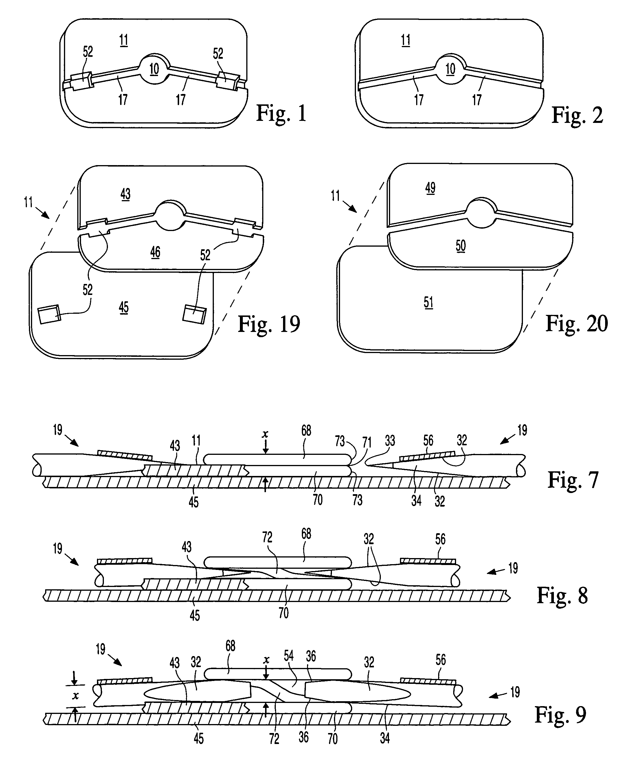
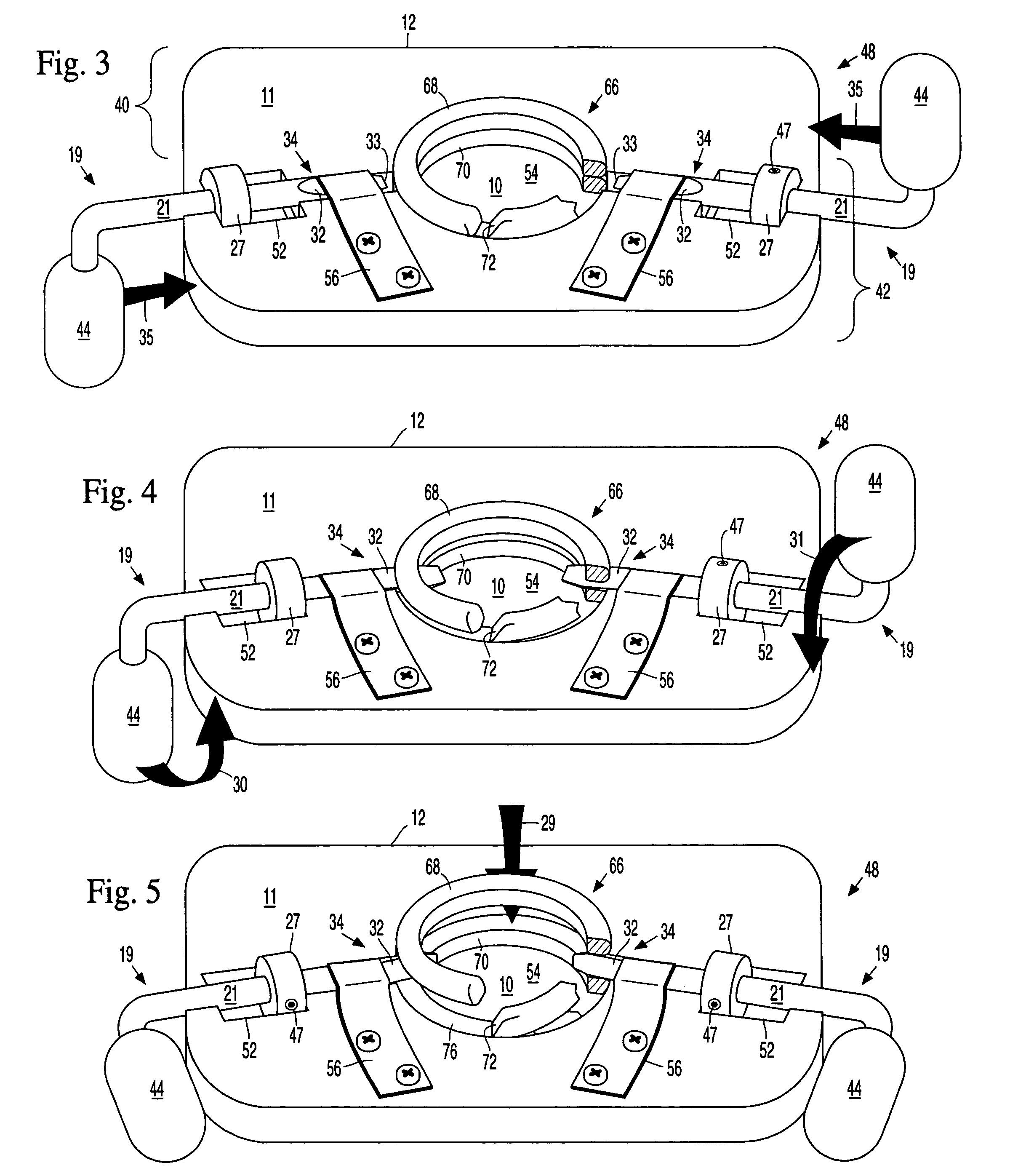
[0052]Each coil-spreading tool comprises a:[0053]flat plate 11 of an appropriate material and size, which can be molded, cast, or fabricated in one piece (FIGS. 1, 2), or it can be layered sheet materials (FIGS. 19, 20). In the layered embodiment, the top layer 43, 46, 49, 50 thickness is equal to the bottom coil 70 thickness (½ the split ring 66 height. See Guidance Channels 17 below and FIGS. 7, 13, 22). The floor plates 45, 51 can be any appropriate thickness;[0054]clip holding compartment 10 recessed into and centered on flat plate 11, its floor recessed a distance equal to the thickness of bottom coil 70 of split ring 66 when placed therein. Split Ring 66 (in this embodiment, round, 1 inch OD) should fit snugly in clip holding compartment 10;[0055]front platform area (FIG. 3, bracket 40) surrounds the front half of clip holding compartment 10, is flat and serves to guide bag corner 20 (FIGS. 6, 6a, 10, 22) with its bumps into its destination at the 12 o'clock position between t...


PUM


Abstract

A guidance channel radiating from each side of clip holding chamber centered on a flat plate. A prying tool slideably and rotatably held within each guidance channel by a spring strip. A split ring held snugly within the holding chamber. The tool tips are forced between the split ring coils, which are separated further by simultaneous rotation of the prying tool handles 90-degrees in opposite clock directions. A pellet placed inside folded bag material forms a bump. The material with bump is placed between the separated coils into the split ring interior. Reverse 90-degree handle rotation partly closes the coils around the bump. Withdrawing the prying tools completely allows the coils to fully close, capturing the pellet-containing material. Tool stops prevent the tool tips from entering the split ring interior too far into or away from the clip holding chamber. Suspension of the tool and bags facilitates production.

Description

CROSS-REFERENCE TO RELATED APPLICATIONS[0001]This application claims the benefit of PPA Ser. No. 60 / 367,036 filed 2002 Mar. 23 by the present inventorBACKGROUND[0002]1. Field of Invention[0003]This invention relates to split ring coil separating tools, and particularly to improvements to applicant's coil separating tool and method as disclosed in his U.S. Pat. No. 5,957,354 issued Sep. 28, 1999.[0004]2. Prior Art[0005]Applicant's issued patent (FIG. 2, split ring spring clip 66, and FIGS. 4a, 4b, 4c, 4d, 4e, 4f, tool 34) discloses a stitchless fastener which is constructed and operates as follows: a pellet is placed inside a folded high strength material, which creates a bump. Once the coils are separated, the folded bump sandwich is inserted between the coils and into the interior periphery of a split ring (like a key ring) whose coils are so powerful they can only be parted with a prying tool. Tool withdrawal permits the coils to close, thereby trapping the pellet-containing mater...

Claims


Application Information

Patent Timeline
Patent Type & Authority Patents(United States)
IPC IPC(8): B23P19/04A45F3/02
CPCA44B15/007A45C13/00B25B33/00Y10T29/53613A45F3/00A45C13/001
Inventor MENTKEN, ROBERT
Owner MENTKEN ROBERT
Why Eureka
Try Eureka