
Hydraulic pressure transducer and hydraulic system

a technology of hydraulic system and transducer, which is applied in the direction of mechanical power devices, mechanical equipment, machines/engines, etc., can solve the problems of limited ability to generate mechanical or electrical energy from low grade heat, low overall efficiency of systems based on organic rankine cycles, kalina cycles and sterling cycles, and no existing technology that could combine an acceptable efficiency. achieve the effect of reducing the pressure in the pressurized fluid, reducing the overall efficiency, and simplifying the means of electrical generators

Active Publication Date: 2015-10-27
ATLAS COPCO AIRPOWER NV
View PDF21 Cites 0 Cited by
  • Summary
  • Abstract
  • Description
  • Claims
  • Application Information

AI Technical Summary

Benefits of technology

The system achieves efficient energy generation with low-grade heat sources, optimizing process performance and extending the technical lifetime of the power station system by reusing heat and monitoring operational conditions.

Problems solved by technology

The possibility to generate mechanical or electrical energy from low grade heat is limited.
Existing systems based on techniques such as Organic Rankine Cycles, Kalina Cycles and Sterling Cycles suffers from very low overall efficiency when the temperature on the input heat decreases below 60° C. There are no existing technologies that could combine an acceptable efficiency at a competitive cost.

Method used


Image

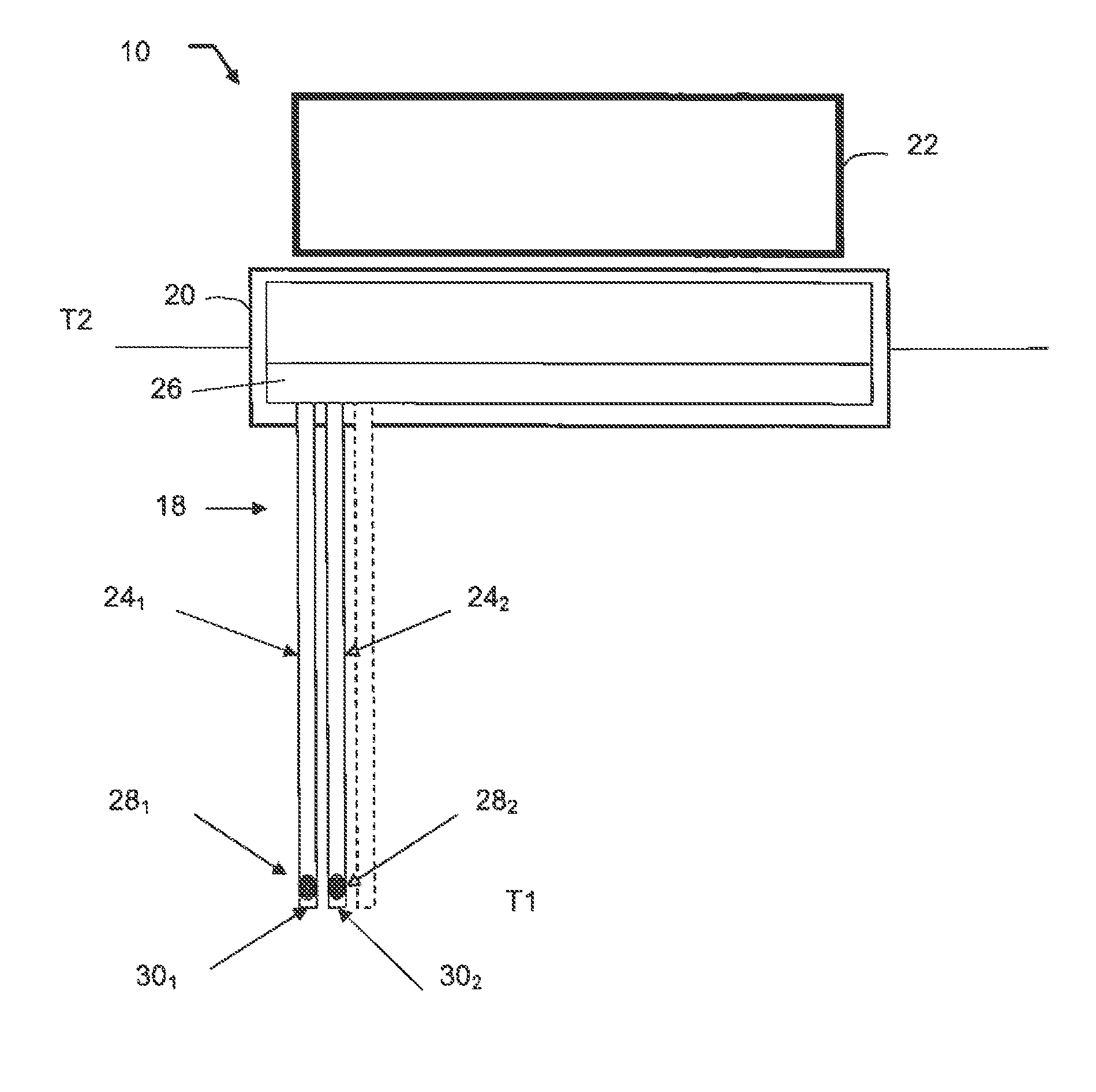
  • Hydraulic pressure transducer and hydraulic system
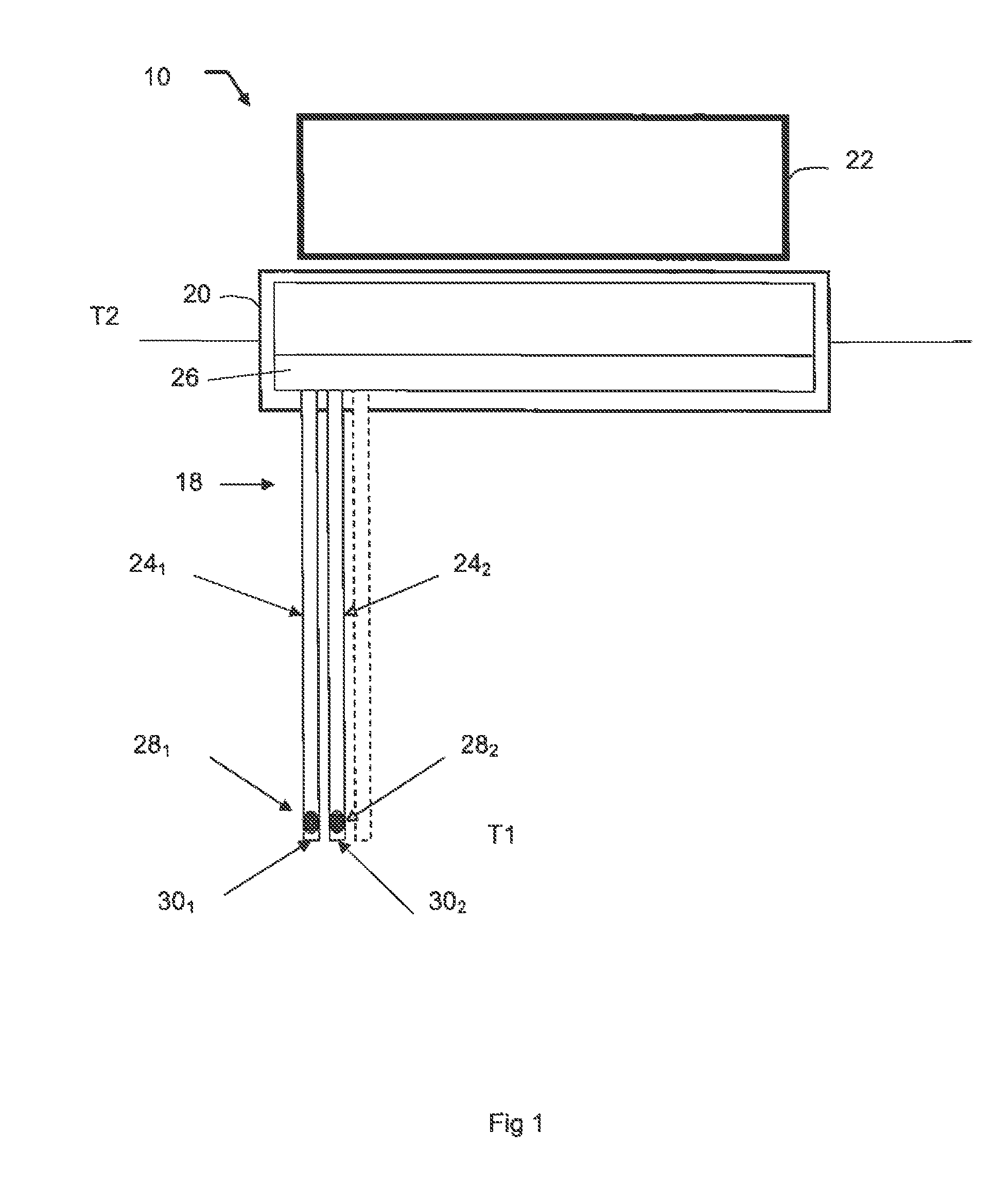
  • Hydraulic pressure transducer and hydraulic system
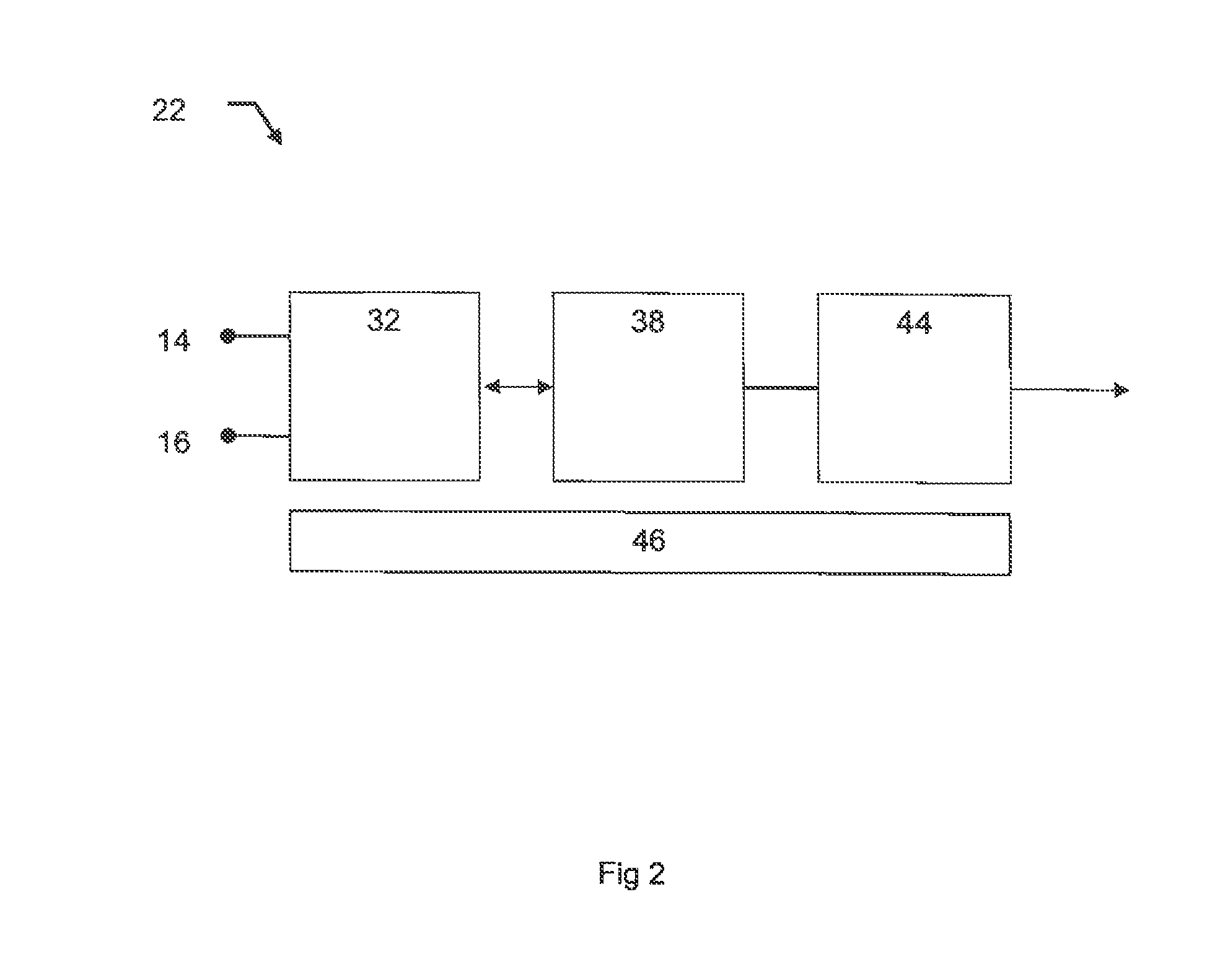
  • Hydraulic pressure transducer and hydraulic system

Examples


first embodiment

[0056]In FIG. 8 there is disclosed a block diagram of a hydraulic system 38. The embodiment disclosed in FIG. 8 comprises a hydraulic motor 42 for the working of an electric generator for generating electric energy. Furthermore, the hydraulic system 38 also comprises a first hydraulic pressure producer 21A and a second hydraulic pressure producer 21B, both in hydraulic connection with the hydraulic motor 42. It is pointed out that each of the hydraulic pressure producers 21A and 21B corresponds and is equal to the heat engine system 32 described earlier in this description. The first and second hydraulic pressure producers 21A, 21B are both operable to transfer hydraulic energy to the hydraulic motor 42. As is apparent in FIG. 8, the first and second hydraulic pressure producers 21A, 21B are mutually hydraulically connected in parallel. The first and second hydraulic pressure producers 21A, 21B are arranged for working in cycles so that the first hydraulic pressure producer 21A deli...

second embodiment

[0071]In FIG. 11 there is disclosed a block diagram of a pressure transducer 40 according the present invention. In this embodiment of the pressure transducer 40 there are two closed rooms, each comprising two hydraulic rotating machines A, B. The hydraulic rotating machines A, B are mutually mechanically interconnected in such a way that for each pair of machines A, B and for each closed room, the first machine A can run the second machine B. As is apparent in FIG. 11, the pressure transducer 40 is provided with a hydraulic inlet (Pin) and a hydraulic outlet (Pout). Furthermore, the machine A in the left pair of machines is hydraulically connected to the second, right room, whereas the machine B in the right pair of machines is hydraulically connected to the first, left room. It is pointed out that the embodiment disclosed in FIG. 11 is used for decreasing the pressure of the fluid. Using the same pressure levels as in FIG. 10, in the case disclosed in FIG. 11, i.e. if two pressure...


PUM


Abstract

A power station system operable to generate energy and comprising a heat engine system and a hydraulic system connected thereto. The heat engine system comprises n number of energy cells, wherein n is an integer, and n≧2, a heat source connected to the energy cells, and a cooler means connected to the energy cells. Each energy cell is operable to generate a pressurized fluid when a phase change material (PCM), comprised in each energy cell, changes from solid phase to liquid phase, and the energy cells are operable between a first phase, and a second phase. During the first phase, a first n / 2 of the energy cells produce pressurized fluid, and a second n / 2 of the energy cells are cooling down, and during the second phase, the first n / 2 of the energy cells are cooling down, and a second n / 2 of the energy cells produce pressurized fluid. The hydraulic system comprises a pressure transducer, and a hydraulic motor connected thereto, and is operable to generate a constant rotation speed.

Description

RELATED APPLICATIONS[0001]The present application is a U.S. National Phase Application of International Application No. PCT / SE2010 / 050810 (filed 12 Jul. 2010) which claims priority to Swedish Application Nos. 0950555-3 (filed 14 Jul. 2009), 0950556-1 (filed 14 Jul. 2009), 0950557-9 (filed 14 Jul. 2009), 0950558-7, (filed 14 Jul. 2009), U.S. Provisional Application Nos. 61 / 225,220 (filed 14 Jul. 2009), 61 / 225,222 (filed 14 Jul. 2009), 61 / 225,223 (filed 14 Jul. 2009), and 61 / 225,224 (filed 14 Jul. 2009).BACKGROUND OF THE INVENTION[0002]1. Field of the Invention[0003]The present invention relates to a power station system operable to generate energy.[0004]2. Description of the Related Art[0005]The possibility to generate mechanical or electrical energy from low grade heat is limited. Existing systems based on techniques such as Organic Rankine Cycles, Kalina Cycles and Sterling Cycles suffers from very low overall efficiency when the temperature on the input heat decreases below 60° C....

Claims


Application Information

Patent Timeline
Patent Type & Authority Patents(United States)
IPC IPC(8): F01K13/02F04F13/00F01K23/06F02G1/04F01B29/10F15B3/00
CPCF04F13/00F15B3/00F03G7/05F03G7/06Y02E10/30
Inventor OSTLUND, BENGTSVENSSON, ASSARINGVAST, HAKAN
Owner ATLAS COPCO AIRPOWER NV
Learn More