Computer assisted method for the advanced design of bent parts of composite material

a composite material and advanced design technology, applied in the direction of computation using non-denominational number representation, design optimisation/simulation, instruments, etc., can solve the problems of affecting the design process of such parts

Inactive Publication Date: 2012-04-24
AIRBUS OPERATIONS SL
View PDF9 Cites 20 Cited by
  • Summary
  • Abstract
  • Description
  • Claims
  • Application Information

AI Technical Summary

Benefits of technology

[0020]In a second aspect, the aforementioned objects are achieved with software that when it is executed on a computer together with a CAD system or included in it, it enables the automatic or semi-automatic execution of the various stages of the aforementioned method.
[0021]Other characteristics and advantages of the present invention will become evident from the following detailed description of the embodiments, illustrative of their object, together with the accompanying figures.

Problems solved by technology

Even with CAD system functionalities, the process of generating the aforementioned mesh models in CAD systems is a tedious proceeding involving a great deal of repetitive manual work, with the consequent risk of mistakes, especially in the case of bent parts where, with current tools, the solid model of the part is obtained from a 2D mesh model—corresponding to the flat laminate which has to be made by a process of forming and curing to obtain the final part—by means of a process in which the reference lines have to be bent on the flange surfaces, and the areas or plateaux of different thickness, both in the core and in the flanges, having to be manually distributed taking into account all the joins between plateaux and the bending radii, this process being tedious, long and repetitive.
The impossibility of automatically or semi-automatically obtaining the solid model of bent parts of composite materials with the currently available CAD systems from the 2D mesh model of the flat laminate which is obtained in the first stage of manufacture of the said parts, is a drawback that hinders the design processes for such parts.

Method used


Image

  • Computer assisted method for the advanced design of bent parts of composite material
  • Computer assisted method for the advanced design of bent parts of composite material
  • Computer assisted method for the advanced design of bent parts of composite material

Examples


Embodiment Construction

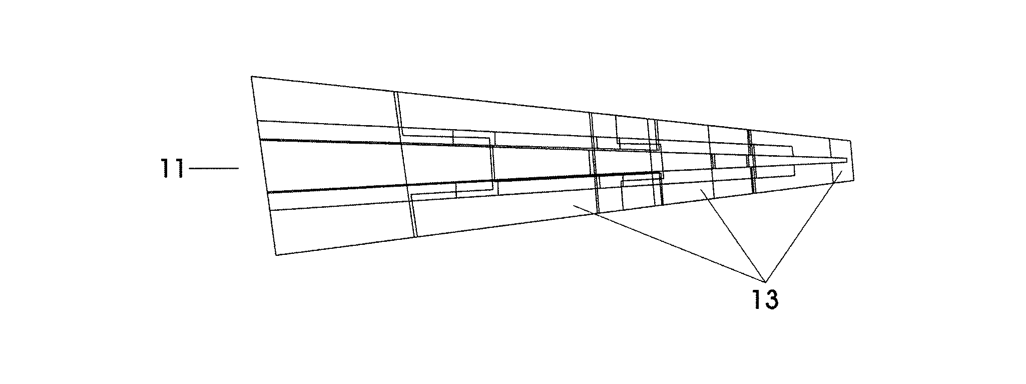
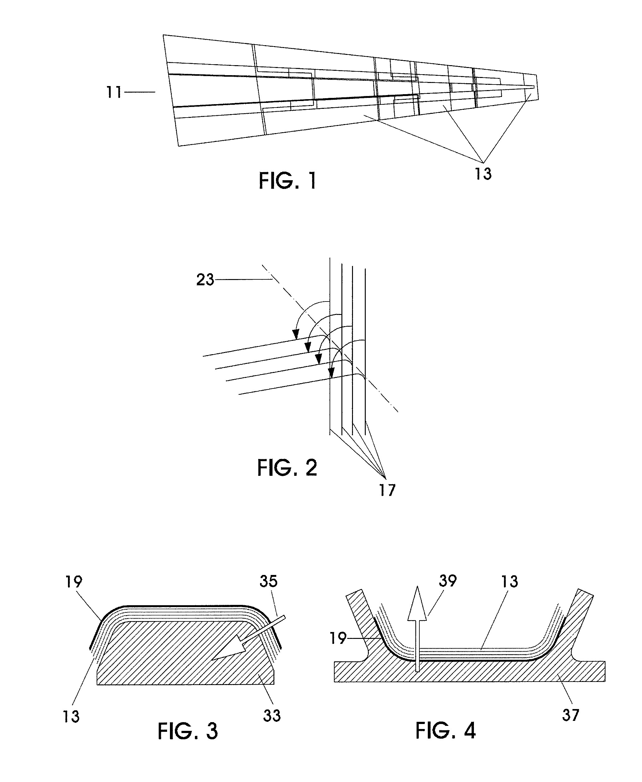
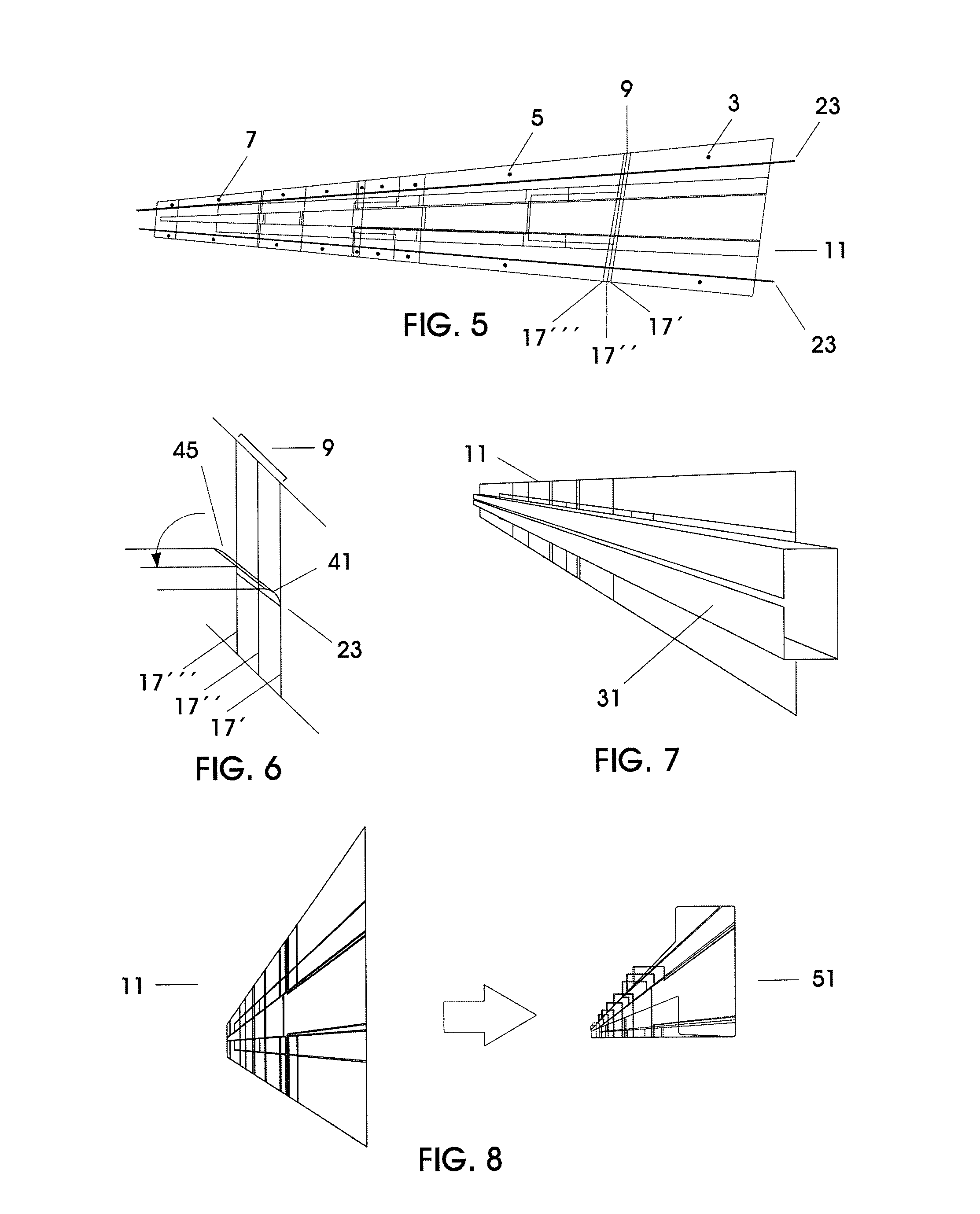
[0032]For a proper understanding of the present invention, the meaning of some of the terms used in this descriptive account are explained.[0033]Bent part: Composite material part manufactured by means of a process comprising a first stage of tape-laying in which a (flat or curved) laminate is obtained and a second stage of forming and curing in which the said laminate is “bent” to obtain the desired shape. We may cite a C-shaped spar of a tailplane torsion box as an example of a bent part used in the aeronautics industry.[0034]Mesh or Pattern: Laminar material used for the formation of the laminate defined by its contour and its position in the laminate, as well as by some physical characteristic such as the alignment of the fibre reinforcement.[0035]2D mesh model: Two-dimensional representation in a CAD system of the meshes that must be stacked to form a flat laminate. One of the purposes of the 2D mesh model is that of providing the necessary information on each one of the meshes...


PUM


Abstract

Computer assisted method for the advanced design of bent parts of composite material using a computer assisted CAD system comprising the following stages: a) Supplying the 2D mesh model (11) of the part; b) Generating the 3D outer surface (19) of the part; c) Obtaining the 3D mesh model (51) by adapting the 2D mesh model (11) to the geometry of the 3D outer surface (19) by bending the contour lines (17) of the patterns (13) of the 2D model (11) with respect to some bending lines (23) set up in relation to a bending surface (31) similar to that of the tool provided for bending the part; d) Generating the solid model (53) of the bent part. The invention also relates to a computer program that when it is executed on a computer together with a CAD system it causes the execution of the method.

Description

FIELD OF THE INVENTION[0001]The present invention relates to a computer assisted method for the advanced design of bent parts of composite material and more particularly to a method that can be used to obtain the solid model of the bent part from the 2D mesh model using a CAD system.BACKGROUND OF THE INVENTION[0002]In some fields of engineering there is a strong trend towards increasing the amount of parts made of composite materials, e.g. in the aeronautical field: wing skins, cover plates and sections of fuselage are parts that can be manufactured using composite materials.[0003]The manufacturing processes for these parts basically comprise a stage of tape-laying, in which layers of a composite material such as prepreg, which is a mixture of fibre reinforcement and polymer matrix capable of storage, are placed in a suitably shaped mould / tool, and a stage of forming and curing.[0004]The composite material may take various forms and in particular the form of a mesh. The composite ma...

Claims


Application Information

Patent Timeline
Patent Type & Authority Patents(United States)
IPC IPC(8): G06F19/00
CPCG06F17/50G06F17/5018G06F2217/42G06F2217/44G06F2113/24G06F2113/26G06F30/00G06F30/23
Inventor BURGOS GALLEGO, RA LDE JULIAN AGUADO, ANTONIO
Owner AIRBUS OPERATIONS SL
Why Eureka
Try Eureka