Coaxial rotor aircraft

a rotor aircraft and coaxial technology, applied in the field of helicopters, can solve the problems of increasing time and expense, increasing the difficulty of helicopter pilots with respect to fixed wing aircraft, and reducing the number of fixed wing pilots, so as to simplify the control requirements, reduce the vibratory load, and facilitate the effect of flying

Active Publication Date: 2012-05-01
AVX AIRCRAFT
View PDF13 Cites 33 Cited by
  • Summary
  • Abstract
  • Description
  • Claims
  • Application Information

AI Technical Summary

Benefits of technology

[0013]In accordance with the present invention, a dual, coaxial rotor helicopter is provided that is relatively easy to fly. Thrust is provided by two ducted fans that are mounted at the rear of the aircraft and spaced apart laterally. Differential thrust generated by the fans provides yaw control for the aircraft, and forward thrust is provided by the fans working in combination. The coaxial rotors are preferably utilized primarily for lift, and not for forward thrust, which simplifies the control requirements. The coaxial rotor with ducted fan configuration also results in lower vibratory loads being imposed on the helicopter, thereby increasing its speed capability. The fan ducts serve to protect the fans, augment the fan thrust at low airspeeds, increase the efficiency of the fans at cruise speeds, and provide horizontal and vertical stabilizing surfaces to ensure aircraft flight stability.

Problems solved by technology

A disadvantage of helicopters with respect to fixed wing aircraft relates to their relative higher difficulty to fly.
Fixed wing pilots seldom become helicopter pilots due to the increased time and expense required to master the additional complexities of helicopter piloting.
This means that fixed wing pilots are often unable to take advantage of the helicopter's ability to be flown into areas not accessible to fixed wing aircraft.
Furthermore, traditional helicopters are much more difficult to fly under instrument meteorological weather conditions (IMC) than fixed wing aircraft, generally limiting their operation under IMC or requiring costly artificial stabilization.
Forward thrust to overcome drag must be provided by the same main rotor that generates the lift for the aircraft which, when combined with the need to control yaw, results in an aircraft that is more complex to control than a fixed wing aircraft.
However, the coaxial rotor aircraft currently available are still relatively complex for a pilot to fly.

Method used


Image

  • Coaxial rotor aircraft
  • Coaxial rotor aircraft
  • Coaxial rotor aircraft

Examples


Embodiment Construction

[0027]It will be appreciated by those skilled in the art that the particular embodiment described herein illustrates the present invention. However, numerous variations on designs details may be made within the scope of the invention, as will become apparent. For example, the embodiment described herein illustrates a two or three place aircraft; however, the aircraft could be any size, larger or smaller, than the example shown.

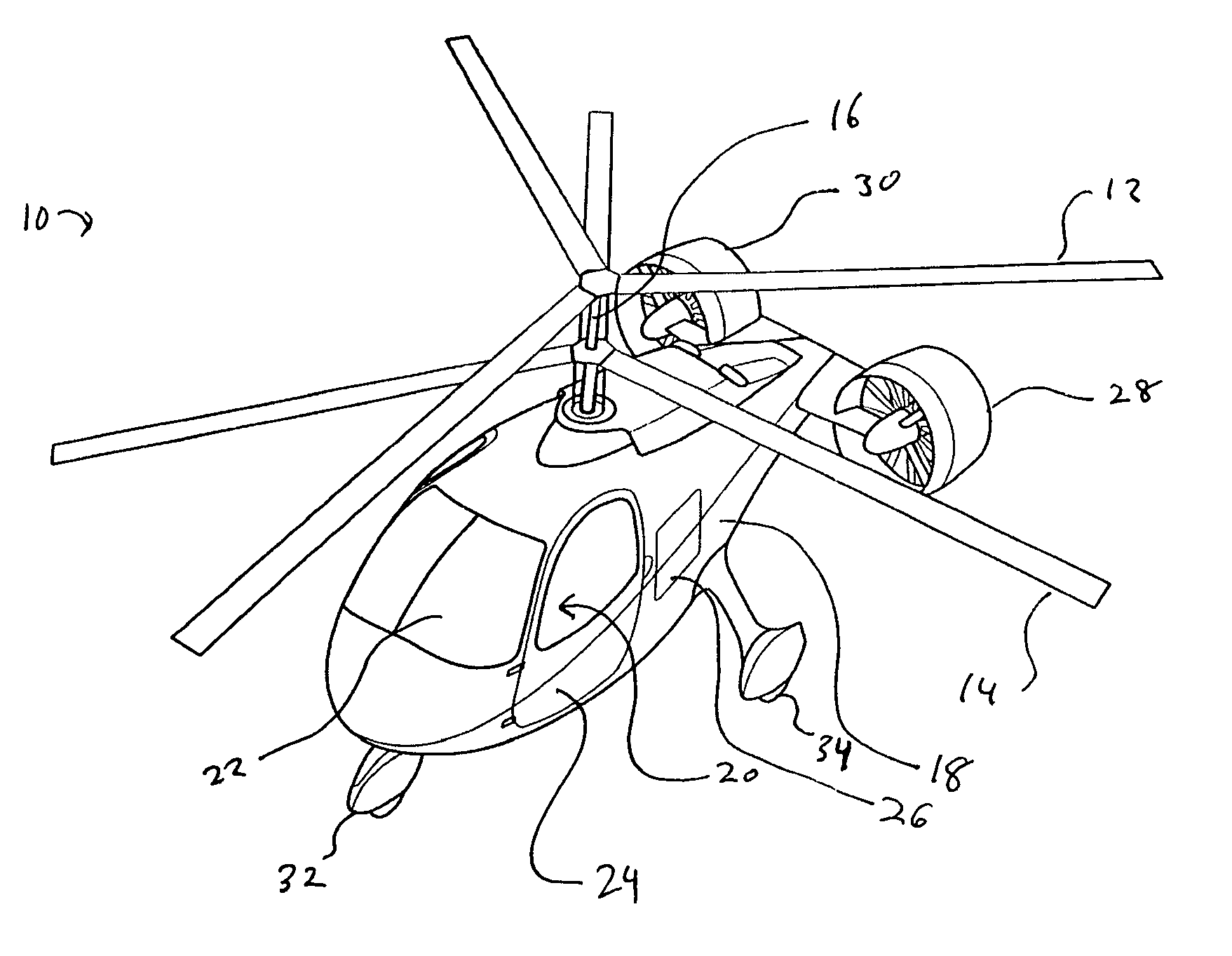
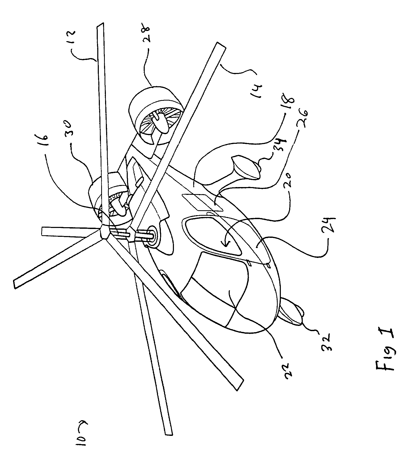
[0028]Referring to FIG. 1, an aircraft designated generally with reference number 10 comprises a helicopter having dual, coaxial rotors for providing lift. An upper rotor 12 and a lower rotor 14 are coaxially mounted and rotate in opposite directions. In the embodiment shown, the upper rotor 12 rotates in the clockwise direction as seen from above, while the lower rotor 14 rotates in the counterclockwise direction. It will be appreciated that reversing the direction of rotation of both rotors will function equally well, and is a matter of design choice.

[0029]R...


PUM


Abstract

A dual, coaxial rotor helicopter is provided that is relatively easy to fly. Thrust is provided by two ducted fans that are mounted at the rear of the aircraft and spaced apart laterally. Differential thrust generated by the fans provides yaw control for the aircraft, and forward thrust is provided by the fans working in combination. The coaxial rotors are preferably utilized primarily for lift, and not for forward thrust, which simplifies the control requirements. The coaxial rotor with ducted fan configuration also results in lower vibratory loads being imposed on the helicopter, thereby increasing its speed capability. The fan ducts serve to protect the fans, augment the fan thrust at low airspeeds, increase the efficiency of the fans at cruise speeds, and provide horizontal and vertical stabilizing surfaces to ensure aircraft flight stability.

Description

CROSS-REFERENCE TO RELATED APPLICATIONS[0001]The present application claims priority from U.S. provisional application No. 61 / 008,829, filed 21 Dec. 2007, the entirety of which is incorporated by reference hereinto.BACKGROUND OF THE INVENTION[0002]1. Field of the Invention[0003]The present invention relates generally to aircraft, and more specifically to an improved helicopter having coaxial, counter-rotating rotors.[0004]2. Description of the Prior Art[0005]Helicopters generally, and coaxial rotor helicopters in particular, have been known and practiced worldwide for many years. Helicopters have many advantages over fixed wing aircraft, including the ability to take off and land vertically, and to maneuver horizontally in any direction while airborne, including while in a hover at zero or near zero speed. This gives them a high degree of flexibility with regard to landing sites, and the ability to transport passengers and cargo to locations not accessible by fixed wing aircraft.[00...

Claims


Application Information

Patent Timeline
Patent Type & Authority Patents(United States)
IPC IPC(8): B64C27/82
CPCB64C27/10B64C27/14B64C27/82B64C2027/8227B64C2027/8236B64C2027/8254B64C2027/8281
Inventor BRODY, DAVID E.GAFFEY, TROY M.RIXEN, FRANKMURRAY, RICHARD F.
Owner AVX AIRCRAFT
Why Eureka
Try Eureka