Bone screw and associated assembly and methods of use thereof

a technology of bone screw and associated assembly, which is applied in the field of bone screw, can solve the problems of subtle damage to the support rod, limited angulation of prior systems,

Active Publication Date: 2012-05-01
INNOVATIVE DELTA TECH LLC
View PDF84 Cites 103 Cited by
  • Summary
  • Abstract
  • Description
  • Claims
  • Application Information

AI Technical Summary

Benefits of technology

[0010]It is, therefore, an aspect of the present invention to provide a bone screw assembly that provides an increased amount of allowable angulation between a spinal stabilizer rod and the screw axis.
[0011]In addition, it is another aspect of the present invention to provide a bone screw assembly that provides a mechanism of attachment of a spinal stabilizer or support rod to a bone screw that minimizes the possibility of damage to the rod by a set screw securing the rod to the bone screw.
[0012]It is still another aspect of the present invention to provide a bone screw that may be placed prior to housing placement, thereby allowing the screw system to be used in minimally invasive surgery.
[0013]In general, one embodiment of the present invention provides a bone screw assembly comprising a bone screw having a shaft and a head assembly, a stabilizer retainer adapted to engage the head of the bone screw, a set screw adapted to contact the stabilizer retainer, and a housing having a proximal opening and a distal opening that open on an interior cavity. The stabilizer retainer is generally cylindrical in shape with a cylindrical channel therein adapted to receive a stabilizer. The stabilizer retainer has flexible portions that allow passage of the stabilizer into the channel. An arcuate wall of the channel is adapted to maintain contact with at least a majority of the stabilizer located within the channel. The housing has a proximal opening and a distal opening that open on an interior cavity. The housing is adapted to receive the bone screw, the stabilizer retainer and the set screw in the interior cavity. The housing has a channel adapted to permit the passage of the stabilizer through the housing, and the housing is adapted to secure the set screw in the distal opening. The set screw and stabilizer retainer are adapted to engage in such a way that movement of the flexible portions of the stabilizer retainer is prevented, thereby maintaining contact between the stabilizer and the wall of the stabilizer retainer channel such that movement of the stabilizer from the stabilizer retainer is prevented.
[0019]In the present invention, it is not necessary for there to be additional spaces or slots in the housing, other than the channel for passage of the stabilizer through the housing, to provide proper placement and securing of the stabilizer. Therefore, in certain embodiments, the housing includes walls adjacent to the housing channel that consist of two opposed, continuous, arcuate segments. Similarly, the present invention eliminates the need for additional spaces or slots in the stabilizer receiver to provide proper placement and securing of the stabilizer in the stabilizer retainer. Therefore, in certain embodiments, the stabilizer retainer includes walls adjacent to the stabilizer retainer channel that consist of two opposed, continuous, arcuate segments. These walls may also comprise the flexible portion of the stabilizer retainer.
[0021]The present invention also provides a method treating a patient where the method includes attaching the bone screw assembly of the present invention to a bone of the patient. The design of the bone screw assembly of the present invention provides the advantage to a surgeon of providing a subtle tactile feedback of a positive lock of components when they are properly positioned. This includes a tactile feedback of the stabilizer locking into place in the stabilizer retainer and / or of the head clamp locking into place on the head base.

Problems solved by technology

However, prior systems have been limited in the amount of angulation permitted relative to the place of attachment to the spine.
This contact causes subtle damage to the support rod caused by plastic deformation of the rod by the set screw.

Method used


Image

  • Bone screw and associated assembly and methods of use thereof
  • Bone screw and associated assembly and methods of use thereof
  • Bone screw and associated assembly and methods of use thereof

Examples


Embodiment Construction

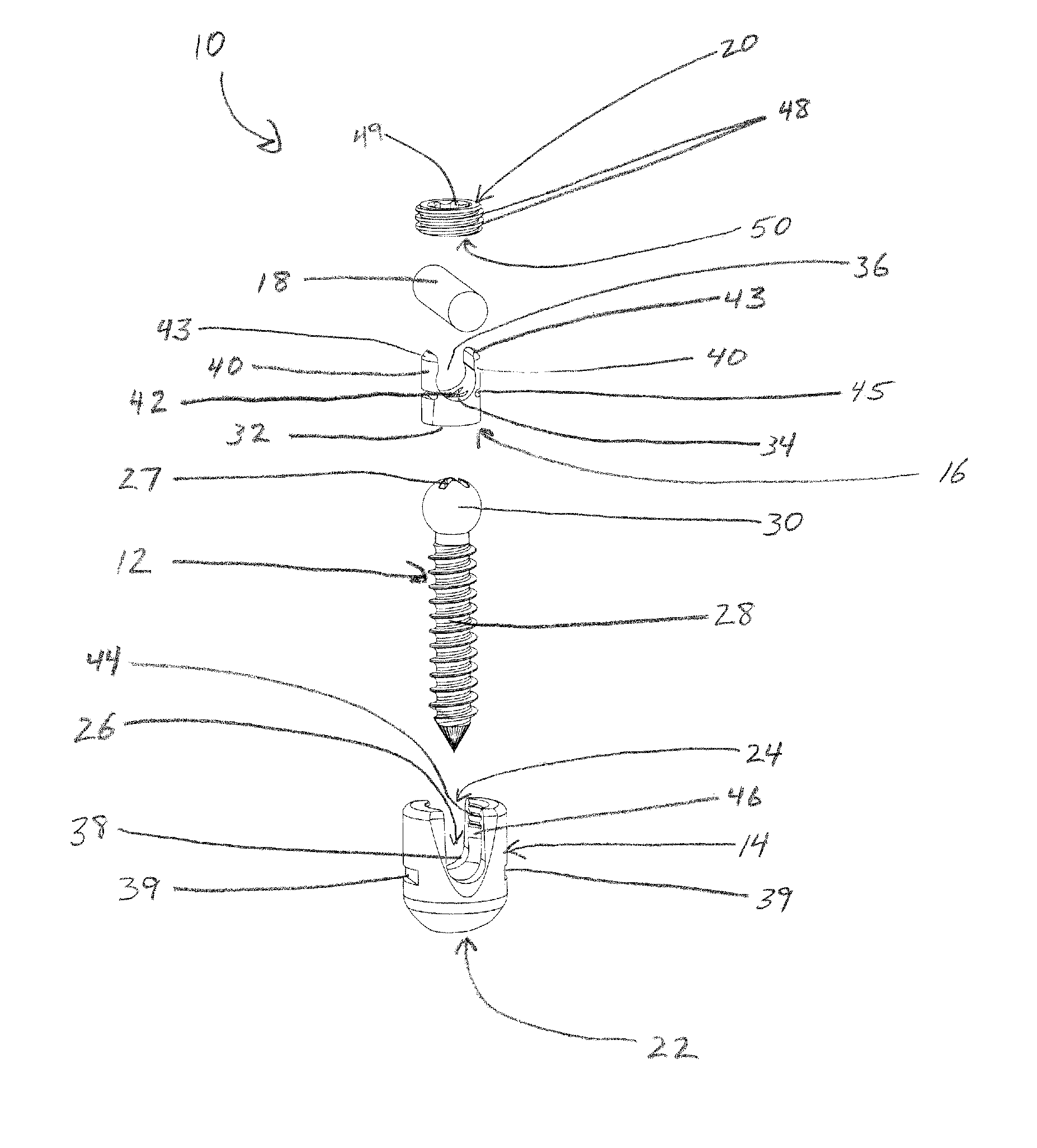
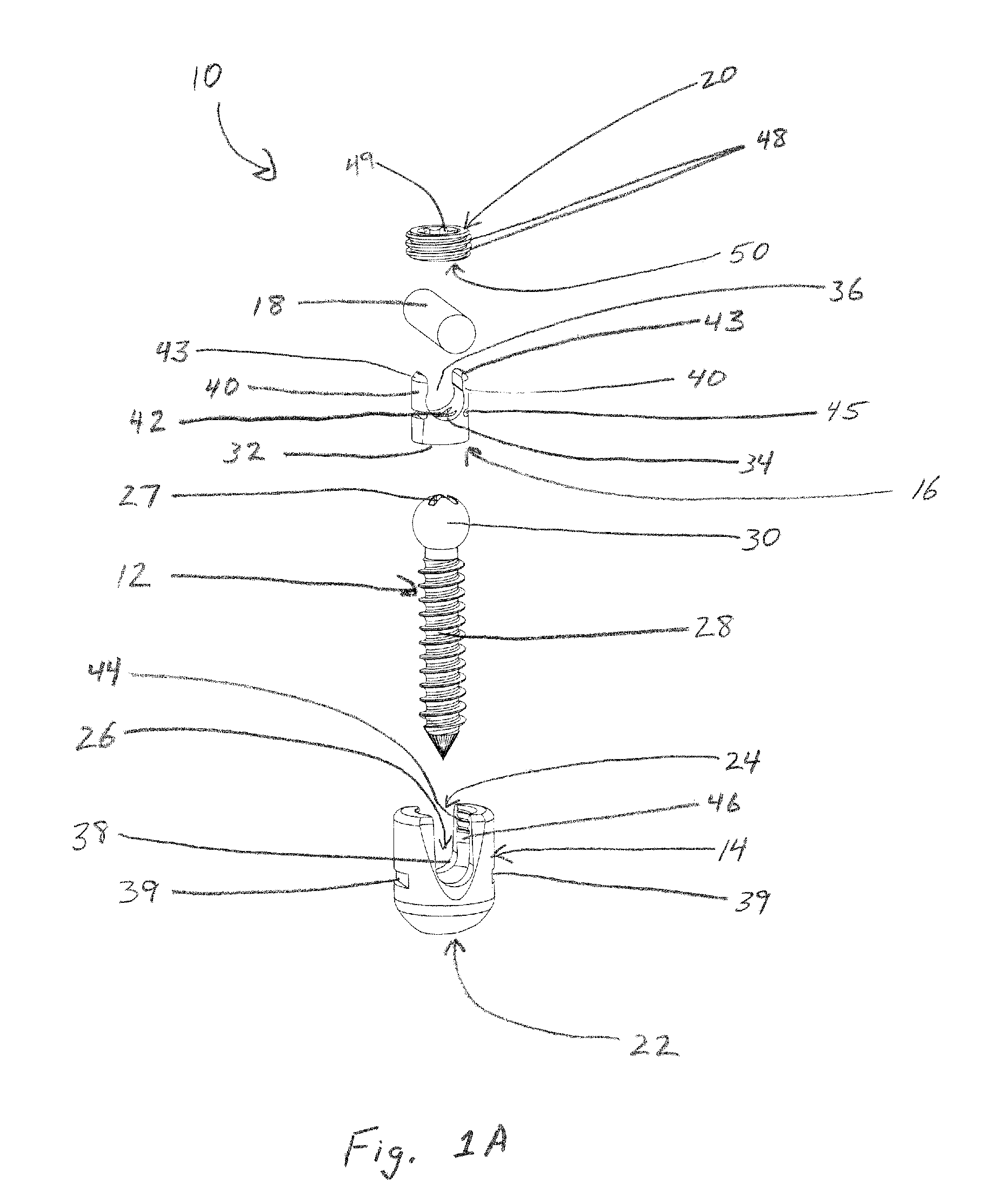
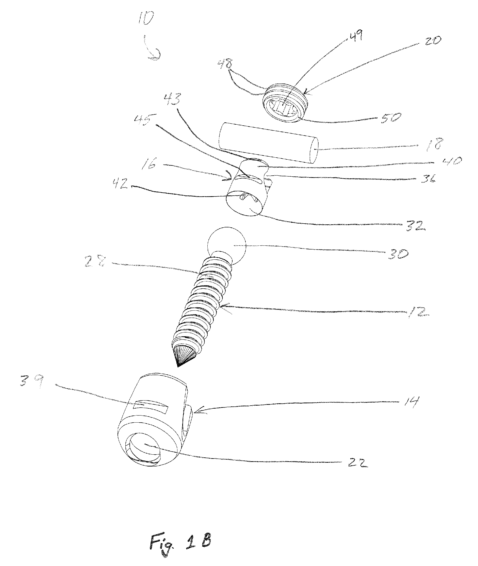
[0051]The present invention is directed toward a bone screw and an associated assembly, especially for application in the spinal stabilization arena. The following examples should not be viewed as limiting the scope of the invention. The claims will serve to define the inventions. Additionally, it should be noted that elements of one example may be combined with elements of another example, except where the function of the components prohibits such combination. The following examples are non-limiting therefore in their arrangements and combinations of elements.

[0052]As shown in the Figures, a bone screw assembly 10 comprises a bone screw 12 and a housing 14. Bone screw 12 has two portions, a shaft 28 and a head 30. In the examples shown, housing 14 is generally cylindrical, with a single central axis, with a proximal opening 22 and a distal opening 24 accessing an interior cavity 26. Interior cavity 26 is generally cylindrical. However, the lower end of cavity 26 adjacent to proxima...


PUM


Abstract

A bone screw assembly comprises a bone screw having a shaft and a head, a stabilizer retainer, a set screw, and a housing having a proximal opening, biased to one side, and a distal opening that open on an interior cavity. The stabilizer retainer has a cylindrical channel that receives a stabilizer. The retainer has flexible portions that allow passage of the stabilizer into the channel. An arcuate wall of the channel maintains contact with the stabilizer within the channel. The housing is adapted to receive the bone screw, the stabilizer retainer and the set screw in the interior cavity. The housing has a channel that permits passage of the stabilizer though the housing. The set screw is engaged in the distal opening. The set screw and stabilizer retainer engage and prevent movement of the flexible portions, preventing movement of the stabilizer from the stabilizer retainer.

Description

BACKGROUND OF THE INVENTION[0001]This invention relates to fixation devices for the spinal column. More particularly, this invention relates to a bone screw and associated components that may also be referred to as a pedicle screw assembly.[0002]The spine is formed of a series of bones called vertebrae. There are 33 vertebrae, which are grouped as cervical, thoracic, lumbar, sacral, and coccygeal vertebrae, according to the regions of the spine they occupy. A typical vertebra consists of two essential parts, an anterior segment or body, and a posterior part, or vertebral or neural arch. These two parts enclose a foramen, the vertebral foramen. Together, the vertebral foramen of the vertebrae form a canal for the protection of the spinal cord. The vertebral arch consists of a pair of pedicles and a pair of laminae.[0003]The body is the largest part of a vertebra, and is more or less cylindrical in shape. Its upper and lower surfaces are flattened. In front, the body is convex from si...

Claims


Application Information

Patent Timeline
Patent Type & Authority Patents(United States)
IPC IPC(8): A61B17/70
CPCA61B17/7032A61B17/7037A61B17/7038A61B17/704
Inventor NILSSON, CARL MICHAEL
Owner INNOVATIVE DELTA TECH LLC
Why Eureka
Try Eureka