Covert sensor emplacement using autorotational delivery mechanism

a technology of autorotational delivery and sensor emplacement, which is applied in the field of astronautics and astronautics, can solve the problems of exposing the payload and the delivery vehicle to unapproved scrutiny, both of these approaches have serious accuracy drawbacks, and the existing system suffers from accuracy susceptibility

Active Publication Date: 2012-05-08
BAE SYST INFORMATION & ELECTRONICS SYST INTERGRATION INC
View PDF23 Cites 221 Cited by
  • Summary
  • Abstract
  • Description
  • Claims
  • Application Information

AI Technical Summary

Benefits of technology

[0014]The system of the present invention solves the emplacement problem with a low-cost, silent configuration that can be adapted to precisely and silently launch any size payload or dispenser and guide it to a soft touchdown at a precise target locality. The subject system accomplishes those goals by deploying sensors on an autogiro that controls the descent to be along a calculated optimum trajectory. The system relies on the autorotational principle embodied in traditional helicopter design and merges those techniques with low-cost manufacturing and low radar cross-section materials to provide a sensor delivery system that is deployable at a variety of altitudes, has a GPS engine to provide instantaneous payload location, calculates the trajectory to a target location from the GPS-derived location, and uses an autogiro autopilot to control the descent of the payload to guide the payload along the trajectory to a precise, soft landing.
[0015]More particularly, the subject invention incorporates a covert acoustically muted system of emplacing sensors at a predetermined target location by deploying the sensor from a height above the target area and controlling its descent while at the same time steering the sensor to the target. This is accompanied by utilizing a GPS or other location determining engine at the sensor payload vehicle to ascertain where the payload is when deployed, and to monitor its trajectory toward a pre-entered target coordinate, with an onboard navigation unit calculating an optimal trajectory based on pre-release conditions, and guiding the payload post-release along the optimal trajectory. Realtime location is provided to the navigation unit that includes an autopilot. In one embodiment, the deceleration of the payload is provided by the autogiro autorotational delivery mechanism that involves a free wheeling rotor with blades controlled by the autopilot to guide the payload to the intended target. In one embodiment, the autogiro is controlled by an autopilot copied to a GPS receiver to provide an optimal payload trajectory, with the autogiro mechanism acting like an unpowered helicopter in an autorotation mode, thus to accurately emplace the sensors and to minimize damage during landing.

Problems solved by technology

Unfortunately, both of these approaches have serious drawbacks relating to accuracy in the case of the parachute delivery approach and high impact loads in the case of the free fall technique.
Furthermore, while it is possible to address specific environmental constraints such as winds aloft under certain conditions, both of the existing systems suffer from accuracy susceptibility due to limited control authority or lack of apriori information.
Finally, in the case of the parachute system, two additional drawbacks are hang time, which optically exposes the payload and delivery vehicle to unwanted scrutiny for long periods of time, and the physical size of the deployment mechanism required to ensure emplacement of the payload.
Additional post deployment issues with observability of a large parachute canopy further spoil observability.
More particularly, the problem in covertly emplacing relatively fragile sensors is the ability to air launch the sensors, have a controlled descent to limit their downward velocity and have them placed at a precise geophysical location which has been pre-targeted.
It is noted that the payloads envisioned are very sensitive sensors, often employing sensitive imaging cameras or radars, which are subject to damage during parachuting or dead-dropping.
The problem with dead-dropping of payloads is also that the accuracies involved are minimal.
If one does not know where the payload is going to land within a mile of the target due to winds aloft, then precision emplacement is impossible.
Note also that whatever the terminal velocity is, it can damage relatively fragile sensors so that if a rock is hit at high speed there is a substantial risk of damaging the sensitive radar, optical device or other sensor.

Method used


Image

  • Covert sensor emplacement using autorotational delivery mechanism
  • Covert sensor emplacement using autorotational delivery mechanism
  • Covert sensor emplacement using autorotational delivery mechanism

Examples


Embodiment Construction

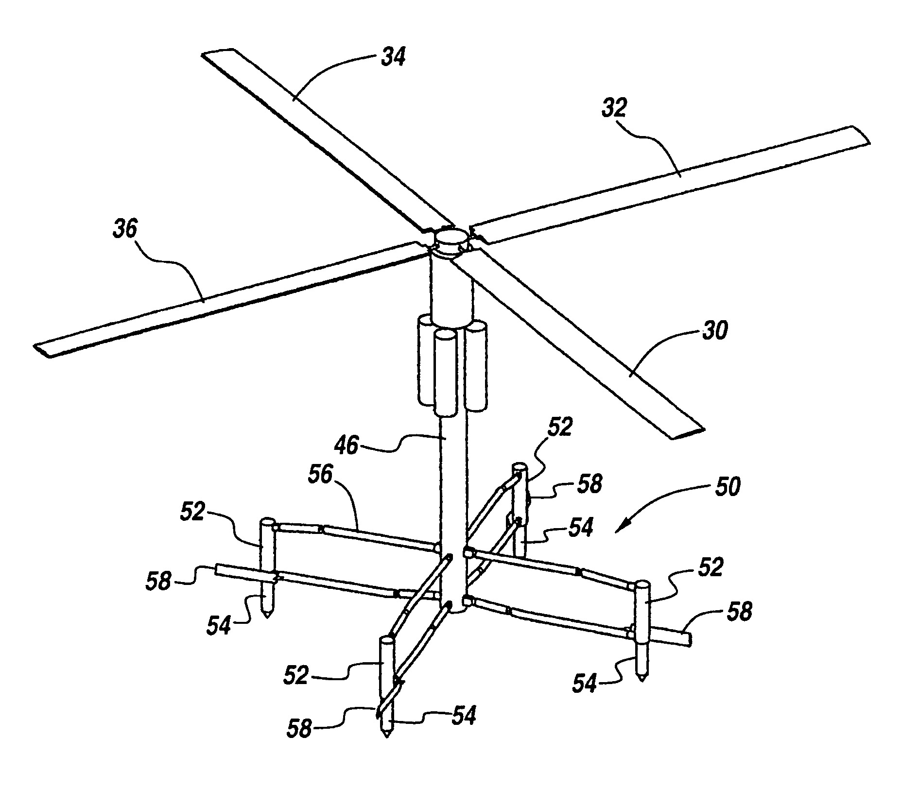
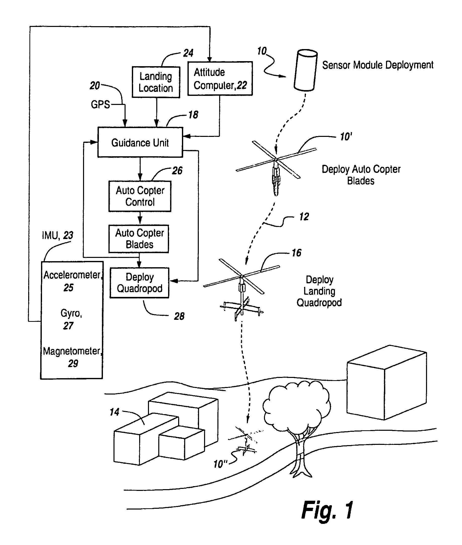
[0029]Referring to FIGS. 1-11, the mechanism of the present invention is a simple modification kit for existing sensors or can be readily incorporated into new sensor payloads to enable heretofore unattainable, precision emplacement of the sensor device at extremely low risk of damage due to high landing loads. The device consists of a guidance and control assembly and mechanical swash plate assembly with attendant rotor blades. The blades are attached in a conventional manner, incorporating a fully articulating hinge. Both cyclic and collective control is provided, enabling a full range of dive speed and directional control to be accommodated. The control is provided via the autogiro navigation and control algorithm hosted in the master processor contained within the electronics module segment of the device. The system navigation approach utilizes GPS techniques with an inertial capability for operation in GPS-denied areas. The blades stow along the longitudinal axis of the payload...


PUM


Abstract

A method for emplacing sensors, comprising the steps of modifying an existing sensor to attach an autorotational mechanism and deploying said sensor by autorotational means.

Description

RELATED APPLICATIONS[0001]This Application is a Continuation In Part and claims rights under 35 USC §120 from U.S. application Ser. No. 12 / 082,371 filed Apr. 9, 2008, which claims rights under 35 USC §119(e) from Provisional Application 60 / 922,458 filed Apr. 9, 2007, the contents of which are incorporated herein by reference.FIELD OF THE INVENTION[0002]The present invention relates to aeronautics and astronautics and, more particularly, to autorotational delivery means for sensor emplacement.BACKGROUND OF THE INVENTION[0003]High accuracy emplacement of fragile electronic sensor payloads for ground or sea monitoring is typically addressed utilizing either free fall or parachute-deployed systems. Unfortunately, both of these approaches have serious drawbacks relating to accuracy in the case of the parachute delivery approach and high impact loads in the case of the free fall technique. Furthermore, while it is possible to address specific environmental constraints such as winds aloft ...

Claims


Application Information

Patent Timeline
Patent Type & Authority Patents(United States)
IPC IPC(8): B64C27/00
CPCB64D19/02F42B12/365F42B15/08G05D1/105G05D1/106
Inventor CARLSON, MARK A.
Owner BAE SYST INFORMATION & ELECTRONICS SYST INTERGRATION INC
Why Eureka
Try Eureka