Alignment device

a technology of aligning device and tibial component, which is applied in the field of aligning device, can solve the problems of increasing the risk of hip dislocation, increasing the risk of tibial component deterioration, and increasing the wear of bearings, so as to enhance the desired performance factor of the patient, quick and accurate aligning implants and tools, and minimising manufacturing costs

Inactive Publication Date: 2012-05-08
MCMINN DEREK JAMES WALLACE
View PDF9 Cites 57 Cited by
  • Summary
  • Abstract
  • Description
  • Claims
  • Application Information

AI Technical Summary

Benefits of technology

[0013]Thus, the present invention provides a simple device that can be used to enable a surgeon to quickly and accurately align implants and tools during surgery. A surgeon, aware of the characteristics of a particular implant and patient, may therefore use the device to guide the implant into a pre-selected position relative to the patient's anatomy, so as to enhance the desired performance factor for that patient's implant.
[0014]The tangible (i.e. physical) nature of the guide component allows embodiments of the device to be formed from a purely mechanical assembly, thereby minimising manufacturing costs and permitting speedy production. Alternatively, embodiments of the device (as described below) may comprise electronic components, such as a laser pointer. However, even such electronic embodiments may be relatively cheap to produce since there is no requirement in the present invention for computer simulation and navigation software.
[0015]Due to the physical nature of the device, being a kit of mechanical and / or simple electronic parts, the complexity of the system is reduced and an alignment procedure can be carried out in a relatively short period of time. In addition, the device can be made in a relatively compact form and can be used in the vicinity of the patient so that the surgeon is not required to continually avert his eyes away from the patient during the operation.
[0029]Moreover, a guide component (i.e. laser pointer) may be aligned with a femoral shaft to thereby align a cutting guide or power saw incorporating a positioning means (i.e. a reflector / reflective surface) to enable an accurate distal femoral cut to be performed. This procedure avoids having to use an intra-medullary rod, as traditionally employed for this type of alignment, and thereby minimises the risk of systematic fat embolisation.

Problems solved by technology

When engaged, it is preferable that the position of the centre of rotation of the bearing elements approximates the centre of rotation of the original anatomical bearing otherwise there will be an increased risk of hip dislocation.
With regard to total knee replacement it is known that varus positioning of the tibial component can deteriorate performance characteristics.
Increased wear of the bearing, increased fracture rate of the tibial base plate and increased loosening rate of the tibial component are all recognized problems with tibial component mal-position.
There are several drawbacks associated with such systems, including the large cost of the equipment, the complexity of the system, the time involved in the positioning procedure and the fact that it requires the surgeon to continually glance at a computer screen and therefore take his eyes away from the patient during the operation.
Primarily due to the expense of the above devices, most surgeons have no option but to align tools and implants by eye.
This can often lead to later complications since the positioning of such elements is uncontrolled and generally inaccurate.

Method used


Image

  • Alignment device
  • Alignment device
  • Alignment device

Examples


Embodiment Construction

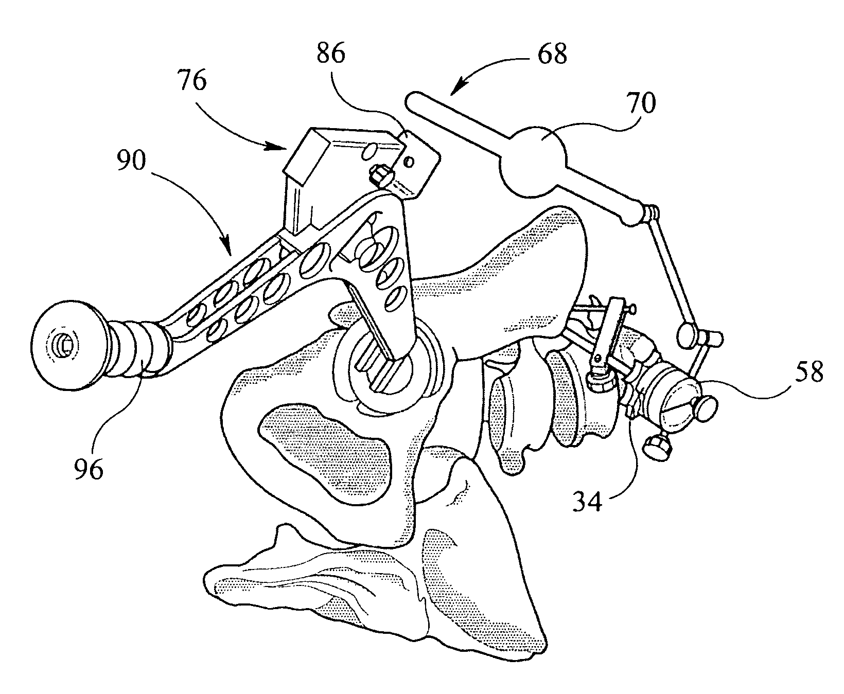
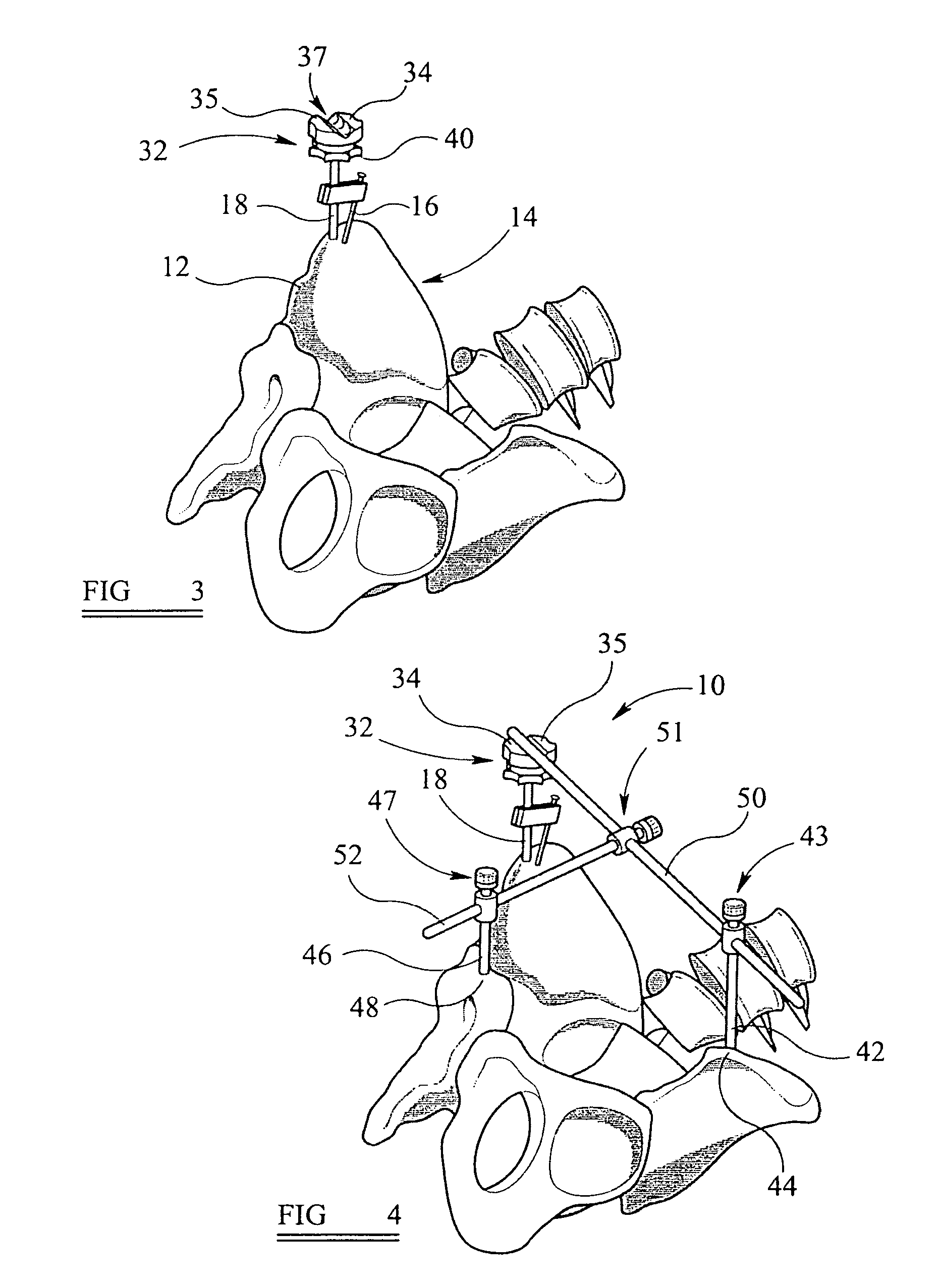
[0049]With reference to FIGS. 1A to 14, there is illustrated an alignment device according to the present invention. The various parts of the alignment device will be described in the order in which they are likely to be used during an alignment procedure. In the example illustrated, the alignment device is employed to align an acetabular cup during a hip replacement operation.

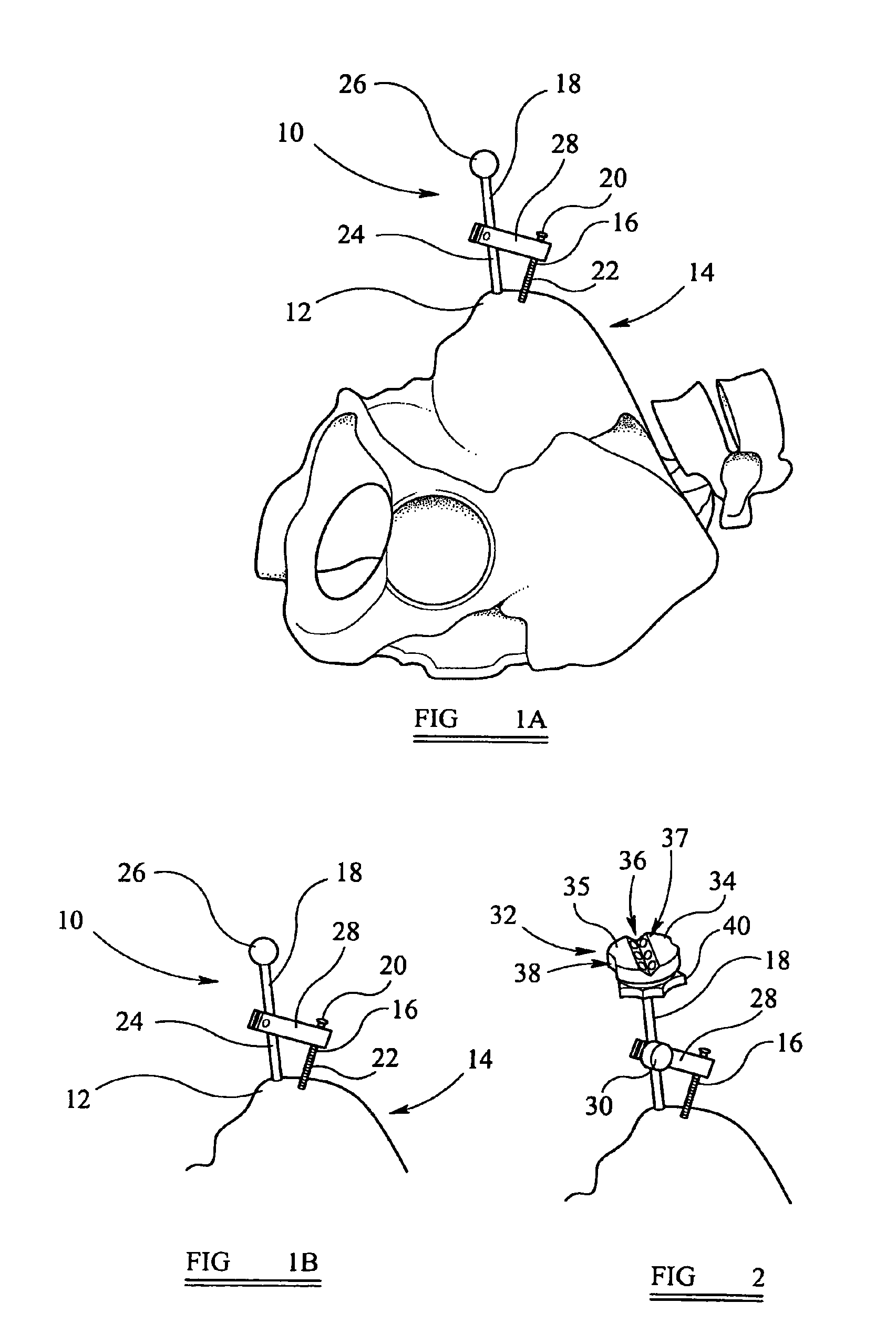
[0050]As shown in FIGS. 1A and 1B, a part of a datum means framework 10 of an alignment device according to the present invention, is attached to the right anterosuperior iliac spine 12 on a patient's pelvis 14. The part of the datum means framework 10 shown comprises a bone screw 16 and a first rod 18. As illustrated more clearly in FIG. 13, the first rod 18 is a single piece comprising a smooth shaft 24 with a substantially spherical ball 26 at one end thereof. The first rod 18 has axial symmetry and is provided with an axial bore, which allows a fixing screw 19 (shown in FIG. 13) to be inserted therethrough...


PUM

PropertyMeasurementUnit
inclination angleaaaaaaaaaa
angleaaaaaaaaaa

Abstract

An alignment device comprises a guide having a tangible guide component, said guide being configured for arranging the guide component at an angle with respect to a reference element; and a positioning means; the positioning means and the guide component being operable to cooperate to position an item at the angle set by the guide component. The alignment device is particularly useful in surgical procedures for the alignment of surgical tools and implants.

Description

CROSS-REFERENCE TO RELATED APPLICATIONS[0001]This application claims priority to and the benefit of United Kingdom patent application Serial No. 0708111.0, filed Apr. 26, 2007, the disclosure of which is incorporated herein by reference in its entirety.FIELD OF THE INVENTION[0002]This invention relates to an alignment device. Particularly, but not exclusively, the invention relates to an alignment device that is suitable for the alignment of tools and implants during surgery.BACKGROUND TO THE INVENTION[0003]During most cases of hip arthroplasty, both bearing elements of the ball and socket joint are replaced with manufactured implants in the form of an acetabular component and a femoral component. There are various designs of these components and they may be manufactured in various materials, have various combinations of geometry and be implanted and fixed by various means.[0004]The acetabular component is usually in the form of a concave partial sphere which functions as a cup or s...

Claims


Application Information

Patent Timeline
Patent Type & Authority Patents(United States)
IPC IPC(8): A61B17/58A61B17/60A61F2/00
CPCA61B17/15A61B17/1746B23D51/025A61B17/141A61F2/4609A61B17/14G01B11/27
Inventor MCMINN, DEREK JAMES WALLACE
Owner MCMINN DEREK JAMES WALLACE
Why Eureka
Try Eureka