Wiper blade

a technology of a blade and a blade body, applied in the field of a blade, can solve problems such as injury risk, and achieve the effects of avoiding injury, avoiding injury, and avoiding injury

Active Publication Date: 2012-05-22
ROBERT BOSCH GMBH
View PDF4 Cites 20 Cited by
  • Summary
  • Abstract
  • Description
  • Claims
  • Application Information

AI Technical Summary

Benefits of technology

[0003]According to the invention, the tip of the gudgeon is protected by parts of the end cap or of the lid against contact both in the open state of the lid and in closed state. For this purpose, skirts running in the longitudinal direction of the wiper blade are expediently integrally formed on the end cap in the region of the gudgeon, said skirts laterally overlapping the gudgeon and running parallel to the head strip when the lid is closed. The skirts prevent a person from unintentionally coming into contact with the tip of the gudgeon and being injured. Without the skirts, there is the risk of injury in particular when a wiper strip has not yet been fitted and the lid is closed, if a finger unintentionally strays into the region of the gudgeon. In order to be able to change the wiper strip and, if appropriate, the support element, which may comprise one spring rail or a plurality of spring rails, it generally suffices if just one end cap per wiper blade is designed in the manner according to the invention. The wiper strip and the support element can then be removed in the longitudinal direction of the wiper blade after said end cap is taken away.
[0004]So that the skirts do not need to be too long, it is expedient for the distance between the skirts to be chosen to be as small as possible, such that they run with little clearance with respect to the head strip. In this case, they are advantageously arranged on the lower sides of guides in which the spring rails serving as the support element are guided. Since the skirts run tightly against the head strip, contact between them and a vehicle window during the wiping is avoided. Despite a relatively small extent in the direction of the gudgeon, good protection against injuries is achieved because of the small intermediate space between the skirts. It thus advantageously suffices for the skirts to extend into the region of lateral support strips of the wiper strip.
[0005]In order also to rule out injuries when the lid is open, it is expedient for the lid not to be connected releaseably to the end cap and for the gudgeon to be fitted in a cutout on the inner side of a top wall of the lid. It is also favorable for the pivoting angle of the lid to be restricted in such a manner that, in the open position of the lid, the tip of the gudgeon is covered by parts of the end cap.

Problems solved by technology

Without the skirts, there is the risk of injury in particular when a wiper strip has not yet been fitted and the lid is closed, if a finger unintentionally strays into the region of the gudgeon.

Method used


Image

  • Wiper blade
  • Wiper blade
  • Wiper blade

Examples


Embodiment Construction

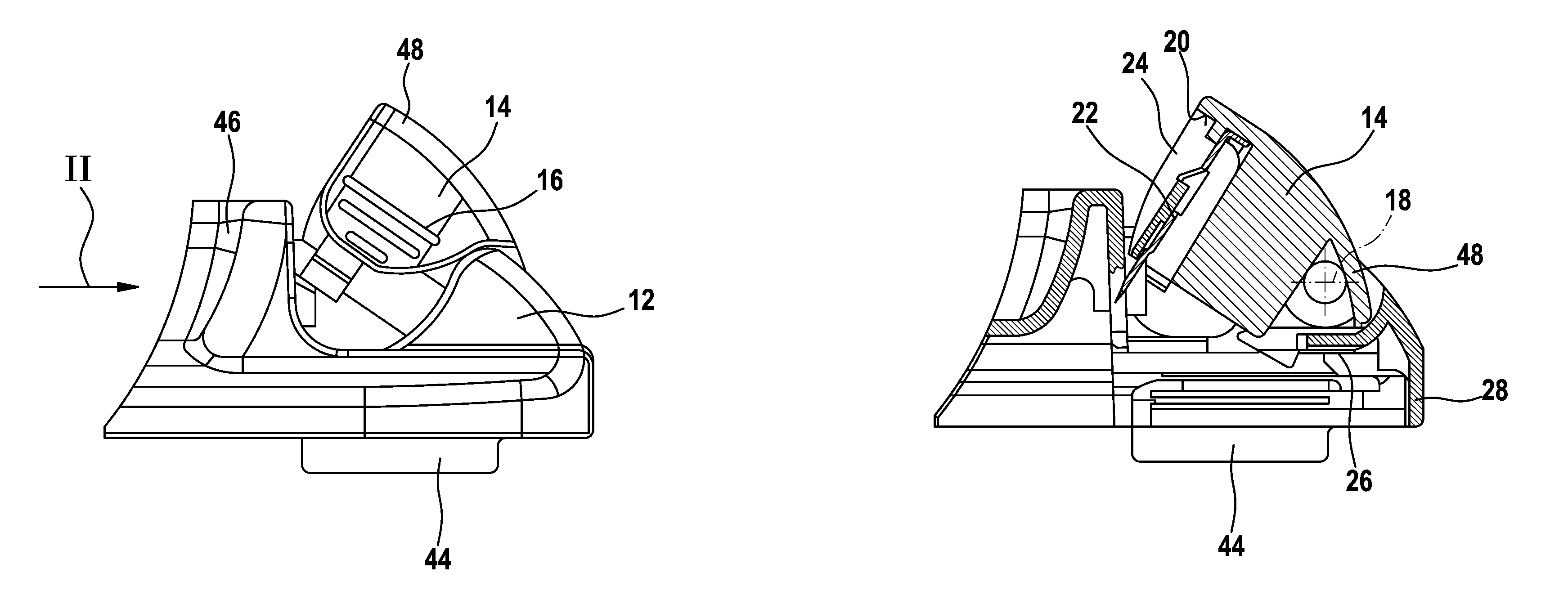
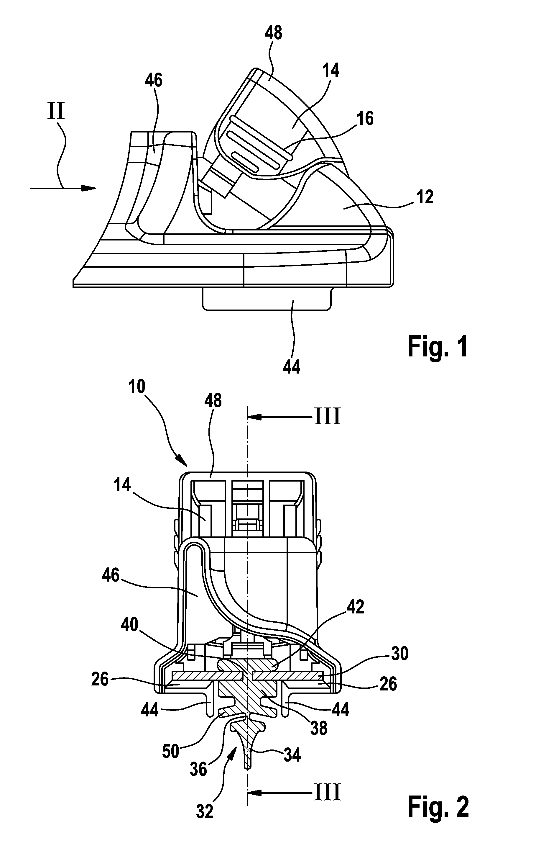
[0012]A wiper blade 10 has a wiper strip 32, the wiper lip 34 of which is connected to a head strip 38 via a tilting web 36. Lateral support strips 50, on which the wiper lip 34 can be supported when it turns over in the end positions of the wiping movement, are located between the head strip 38 and the tilting web 36.

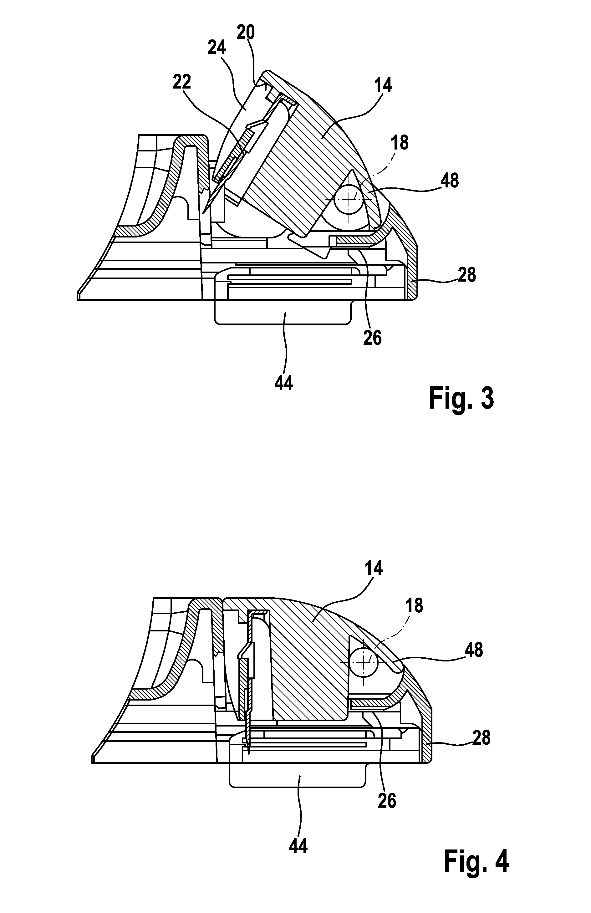
[0013]Longitudinal grooves which form a web 40 between them are provided on the longitudinal sides of the head strip 38. Said web connects a back strip 42 to the remaining part of the head strip 38. Spring rails 30 are inserted, as a support element, into the lateral longitudinal grooves and protrude for a distance laterally out of the longitudinal grooves. A connecting element (not illustrated) for the articulated connection to a wiper arm, a spoiler and end caps 12 can be fitted on the protruding parts of the spring rails 30. The end caps 12 have connecting profiles 46 for a spoiler.

[0014]The end caps 12 sit with guides 26 on the spring rails 30 and hold the latter t...


PUM


Abstract

The invention is based on a wiper blade (10) having a wiper strip (32) and a support element (30) at whose ends endcaps (12) are guided, said endcaps (12) at their end sides (28) facing the ends of the wiper blade (10) extending as far as a wiper lip (34) via the support element (30), wherein at least one endcap (12) has a lid (14) which is connected to the endcap (12) so as to be capable of pivoting about an articulation axis (18) transversely with respect to the wiper blade (10) and has a gudgeon (22) on its side facing the head strip (38), which gudgeon (22) penetrates the head strip (38) when the lid (14) is closed. It is proposed that the tip of the gudgeon (22) be secured by parts of the endcap (12) or of the lid (14) against contact both in the opened state of the lid (14) and in the closed state.

Description

BACKGROUND OF THE INVENTION[0001]The invention is based on a wiper blade.[0002]DE 10 2004 051 467 A1 discloses a wiper blade. Two spring rails serving as a support element are guided in inner guide profiles of the end caps which are closed on the end side facing the end of the wiper blade such that the spring rails are fixed in the longitudinal direction relative to the end caps by the closed end surfaces. The end caps, for their part, are fixed in the longitudinal direction with respect to the head strip of the wiper strip by means of releasable retaining means. The spring rails are therefore also fixed relative to the wiper strip by the end caps. In one exemplary embodiment, the retaining means used between the end cap and the head strip is a needle or a gudgeon which is integrally formed on that side of a lid which faces a wiper strip and, during the installation, penetrates the head strip of the wiper strip as soon as the lid is closed. In the closed position, the lid latches to...

Claims


Application Information

Patent Timeline
Patent Type & Authority Patents(United States)
IPC IPC(8): B60S1/38
CPCB60S1/38B60S1/3891B60S1/3806B60S2001/3822B60S1/3894B60S1/3879
Inventor WILMS, CHRISTIANLAMMENS, KOENVERELST, HUBERT
Owner ROBERT BOSCH GMBH
Why Eureka
Try Eureka