Non-contact optical fiber connector component

a technology of non-contact optical fiber and connector, which is applied in the direction of optical elements, instruments, manufacturing tools, etc., can solve the problems of degrading optical performance, poor performance, and easy apparent weakness of this approach, so as to reduce the cost of ar coating, reduce the transmission loss at air-fiber, and easy coupling

Inactive Publication Date: 2013-06-27
ARRAYED FIBEROPTICS CORP
View PDF24 Cites 43 Cited by
  • Summary
  • Abstract
  • Description
  • Claims
  • Application Information

AI Technical Summary

Benefits of technology

[0013]Each such fiber terminates at an output facet. A tubular ferrule having an output end and a junction end coaxially surrounds the fiber. The fiber output facet has a concave offset relative to the surrounding endwise surface of the ferrule, such that when two aligned abutting ferrules of a fiber coupling device are mutually facing and in contact, a small gap of micron level is present between the fiber facets. The endwise surface of the ferrule is preferably convex. The gap is sufficiently small so as to allow the light to couple easily between the fiber cores for optical communication. To substantially eliminate the transmission loss at air-fiber interfaces, the fiber facets are coated with a durable anti-reflection (“AR”) coating. The means for providing the concave offset can be either an indentation of the fiber relative to the endwise surface of the ferrule or, alternating, a built up spacer on the endwise surface of the ferrule relative to the fiber facet, such as by an annular metal deposit.
[0014]In a preferred embodiment, the fiber inside the AR coated fiber ferrule is bare fiber and therefore causes minimal outgassing in a vacuum AR coating chamber and permits very large number of such ferrules to be coated simultaneously, thereby reducing the AR coating cost for each ferrule assembly. The rear end of the fiber at the above AR coated connector ferrule can be cleaved, and fusion spliced to a typically reinforced fiber cable, as in known splice-on connectors.

Problems solved by technology

In fact the physical contact mechanism worked so well, most researchers of optical fiber connectors did not realize that there could be another physical mechanism to make fiber connectors.
While PC and APC connectors have the significant advantage of easy fiber termination by polishing, the weaknesses of this approach are readily apparent.
For example, contamination between the fibers can easily disrupt the coupling of the light by creating an air gap and particulates can prevent physical contact altogether, leading to poor, unpredictable performance.
In addition, as with any apparatus involving physical contact, repeated coupling of the connectors causes wear and tear, which invariably degrades optical performance over time.
APC connectors have another significant weakness.
If this angle is not sufficiently precise, an air gap will open between the fibers, leading to significant optical loss due to Fresnel reflection.
While the rounded connector facets relax the required angular precision, it is difficult in practice to ensure that the fiber is at the apex of the polish surface, thereby reducing the achievable alignment.
It is generally known that APC connectors have inferior optical performance in insertion loss compared to PC connectors.
Random mating performance is much worse for APC connectors.
However, there can be multiple reflections and interference at the two glass surfaces which tend to make the optical transmission unstable.
Dust, dirt and debris in the expanded optical path now scatter a much smaller fraction of the beam and therefore cause smaller coupling variation.
The drawback to this approach is inferior optical performance in terms of insertion loss and return loss, and significantly higher complexity and manufacturing cost, all as results of significantly increased number of optical elements.
Thus, the benefits come at significantly higher cost.

Method used


Image

  • Non-contact optical fiber connector component
  • Non-contact optical fiber connector component
  • Non-contact optical fiber connector component

Examples


Embodiment Construction

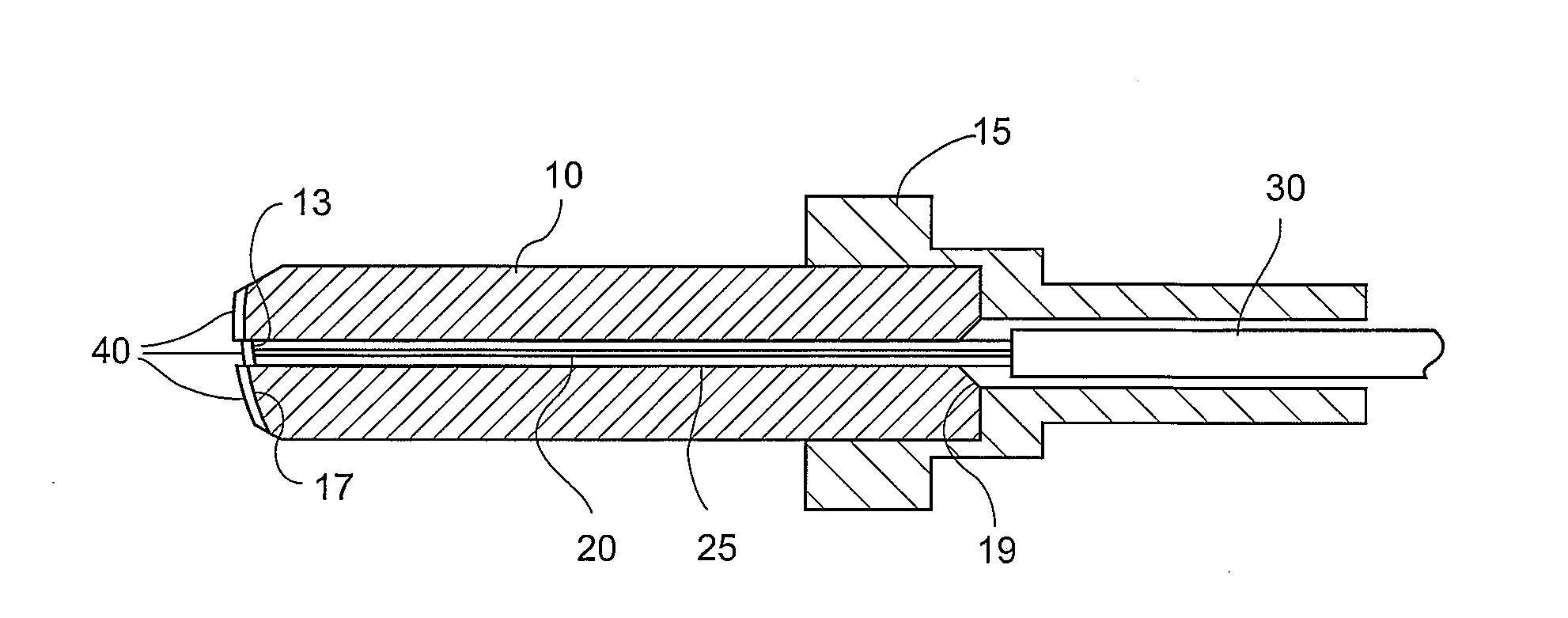
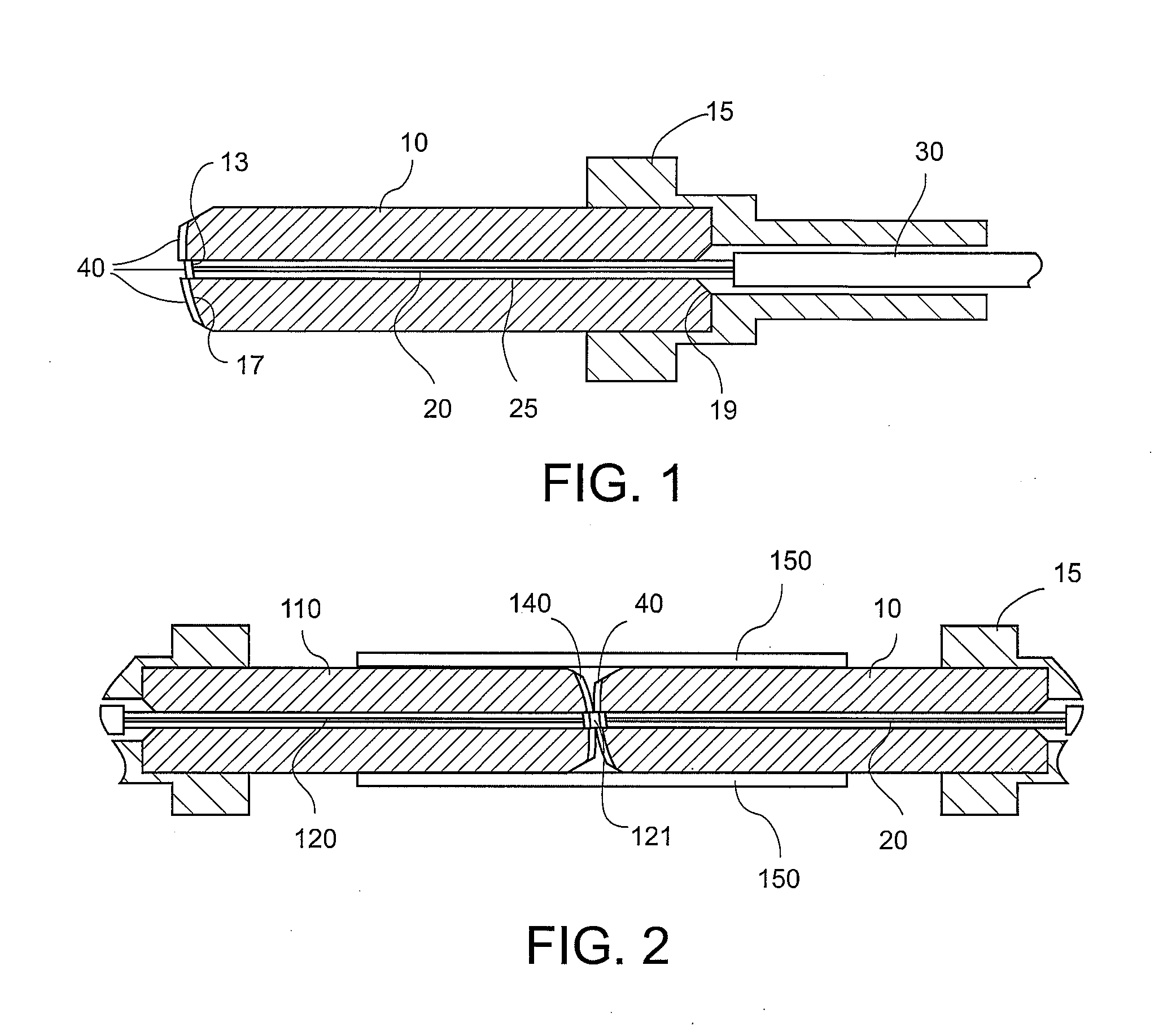
[0023]With reference to FIG. 1, an embodiment of the non-contact optical fiber connector component according to the present invention is a non-contact fiber ferrule assembly for making non-contact optical fiber connectors. An optical fiber 20 is permanently affixed in the axial through hole 25 of a connector ferrule 10 with epoxy, and a metal flange 15 is connected to the ferrule 10. The front surface of the ferrule 17 forms a smooth polished, curved profile with the fiber surface 13 somewhat offset from surface 17. An AR coating 40 is applied over the entire polished surface of the ferrule 17 and the fiber facet 13. The fiber 20 can be any type of optical fiber. For example, it can be single mode fiber, multimode fiber, or polarization maintaining fiber.

[0024]FIG. 2 shows a pair of such non-contact fiber connector components coupled together to complete a fiber connection with the aid of an alignment split sleeve 150 found in a connector adapter. A conventional fiber connector adap...


PUM

PropertyMeasurementUnit
polish angleaaaaaaaaaa
diameteraaaaaaaaaa

Abstract

An optical fiber connector component that is useful for joining and connecting fiber cables, particularly in the field. A joinder component includes a fiber ferrule coaxially housing a short section of optical fiber with a rearward flanged sleeve that allows the fiber to extend through it. Rearwardly the flanged sleeve extends into a connector body where a fusion splice of the fiber section to the main fiber cable is hidden. Forwardly, the fiber facet and ferrule have anti-reflection coatings and are configured so that the fiber has an output facet recessed slightly relative to the forward polished end surface of the ferrule so that when two ferrule end surfaces are brought together in an adapter, respective fiber facets are slightly spaced apart thereby avoiding wear on fiber facets due to physical contact, yet having good optical communication.

Description

CROSS-REFERENCE TO RELATED APPLICATION[0001]This application claims priority from provisional application Ser. No. 61 / 579,017, entitled “Non-Contact Optical Fiber Connector”, and filed on Dec. 22, 2011.TECHNICAL FIELD[0002]The present invention relates to fiber optic connectors in general and in particular to a connector component useful for terminating optical fibers for joinder of optical fiber cables, and the like, in a fiber connector.BACKGROUND ART[0003]In fiber optics based communication systems, it is necessary to have optical fiber connectors with low transmission loss and low back reflection from the fiber to fiber interface. There are two types of optical fiber connectors in general, one type is the predominant fiber connector based on physical contact and we call it “conventional” fiber connector in this application and the other type is called expanded beam connector which utilizes a lens, and is used only in limited applications.[0004]The conventional connector designs ...

Claims


Application Information

Patent Timeline
Patent Type & Authority Applications(United States)
IPC IPC(8): G02B6/36
CPCG02B6/36G02B6/3818G02B6/3822Y10T29/49826G02B6/3847G02B6/3863G02B6/3846G02B6/25G02B6/255G02B6/3881G02B6/3882G02B6/3885G02B6/443G02B6/4471
Inventor JIAN, BENJAMIN B.
Owner ARRAYED FIBEROPTICS CORP
Why Eureka
Try Eureka