Collar rib for heat exchanger header tanks

a heat exchanger and header technology, applied in the field of automotive heat exchangers, can solve the problems of increasing the deflection of the wall in such applications, reducing the stiffness and fatigue resistance of materials, and packaging problems in the vehicle, and achieve the effect of reducing the bending movemen

Active Publication Date: 2012-05-22
VALEO INC
View PDF27 Cites 26 Cited by
  • Summary
  • Abstract
  • Description
  • Claims
  • Application Information

AI Technical Summary

Benefits of technology

[0015]The present invention provides for headering arrangement for a heat exchanger, and, particularly, a heat exchanger headering arrangement comprising a header part and plastic tank part that forms an adequate seal without the need for a header inner flange. Preferably, the present invention provides for a heat exchanger operating at extreme or higher operating pressures and temperatures, such as those found in charge air coolers, inter coolers, after coolers and the like, wherein the offset between the outer flange and the tube is decreased, reducing bending movements in the header caused by internal pressure loading more preferably in inner flange is utilized. Also, surprisingly, the present invention finds advantages in extreme internal lower pressure conditions, such as radiator applications.
[0016]The present invention address and solves problems of the prior art. In preferred embodiments of the present invention the headering arrangement is such that there is no header inner flange. The header inner flange is removed or eliminated. The preferred embodiments of the present invention position inside edges of a tank foot and gasket by the collar that forms the tube ferrule, the collar therefore acting as a ‘rib’ between header slots to stiffen the header and strengthen or protect the thin-walled tube. In further preferred embodiments, a gasket-mating surface (‘gasket’ or ‘lower flange’) is provided coplanar with the header, thus eliminating the header pan.
[0017]In preferred embodiments in accordance with the present invention, the design is very compact; only about twice the header thickness (less thinning due to forming), plus the tank foot width, extends beyond the end of the tube on each side. The preferred embodiments, therefore, comprise at least one collar-style tube ferrule acts as a rib, with a resultant ‘stiffening’ of the header and ‘bridging’ over the tube-to-header joint or seal to reduce stresses in the thin-walled tube. In preferred methods in accordance with the present invention, embodiments with more rigid headers, the more rigid header designs also have been shown to improve the crimping process.

Problems solved by technology

Higher pressures and larger wall surface areas result in greater wall deflection in such applications.
Higher temperatures reduce the stiffness and fatigue resistance of the materials.
These factors contribute to greater structural integrity and durability problems with more extreme temperature and pressure conditions.
Problems identified in the prior art, therefore, include that of a trough (or well) formed in the periphery of the header that tends to increase the overall thickness of the heat exchanger, which can result in packaging problems in the vehicle; and, that of a header width also creates a bending moment, as the offset of the gasket (lower) flange from the header plane generates a second bending moment.
Problems identified in the prior art, therefore, include that of a trough (or well) formed in the periphery of the header tends to increase the overall thickness of the heat exchanger, which can result in packaging problems in the vehicle; and, that of a header width also creates a bending moment, as the offset of the gasket (lower) flange from the header plane generates a second bending moment.
However, the solution of connecting the inner flange to the thin-walled tube can create stress concentrations in the tube under internal pressure which may exceed acceptable limits in some applications.
This, in addition to the problem of internal temperature and pressure conditions in heat exchanger applications, require further solutions not yet found in the prior art.
Tank and header deflection and corresponding stresses can lead to failure in the tank wall, in the header, or in the tube-to-header joint area.
Headering means employing mechanical attachment and sealing methods have been developed, due to the difficulty of effectively welding, brazing or soldering of unlike materials (such as alloy headers with plastics such as those found on radiator header tanks).
While this design has been found to be adequate for many radiator applications, it has many disadvantages which are accentuated, as described above, when used in more extreme, and, particularly, internal high temperature and pressure conditions, such as those found in charge air coolers and the like.

Method used


Image

  • Collar rib for heat exchanger header tanks
  • Collar rib for heat exchanger header tanks
  • Collar rib for heat exchanger header tanks

Examples


Embodiment Construction

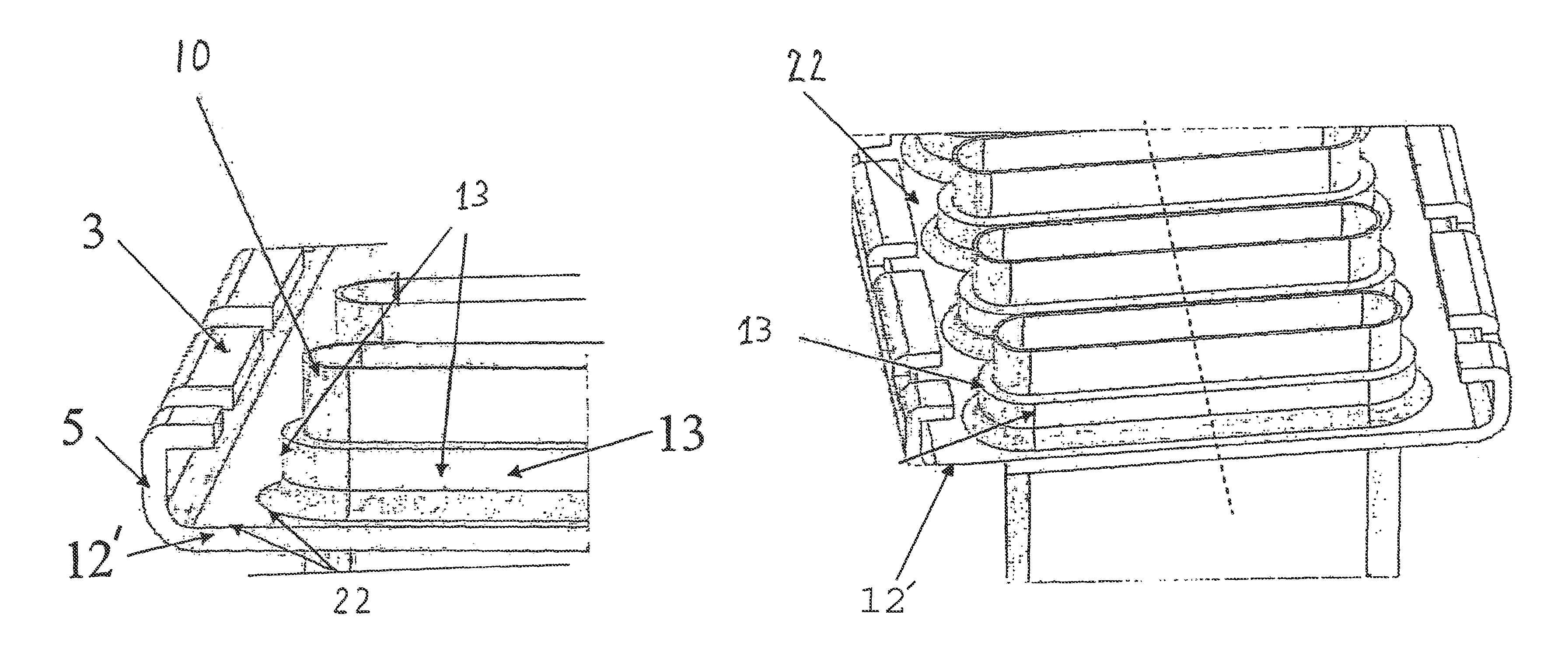
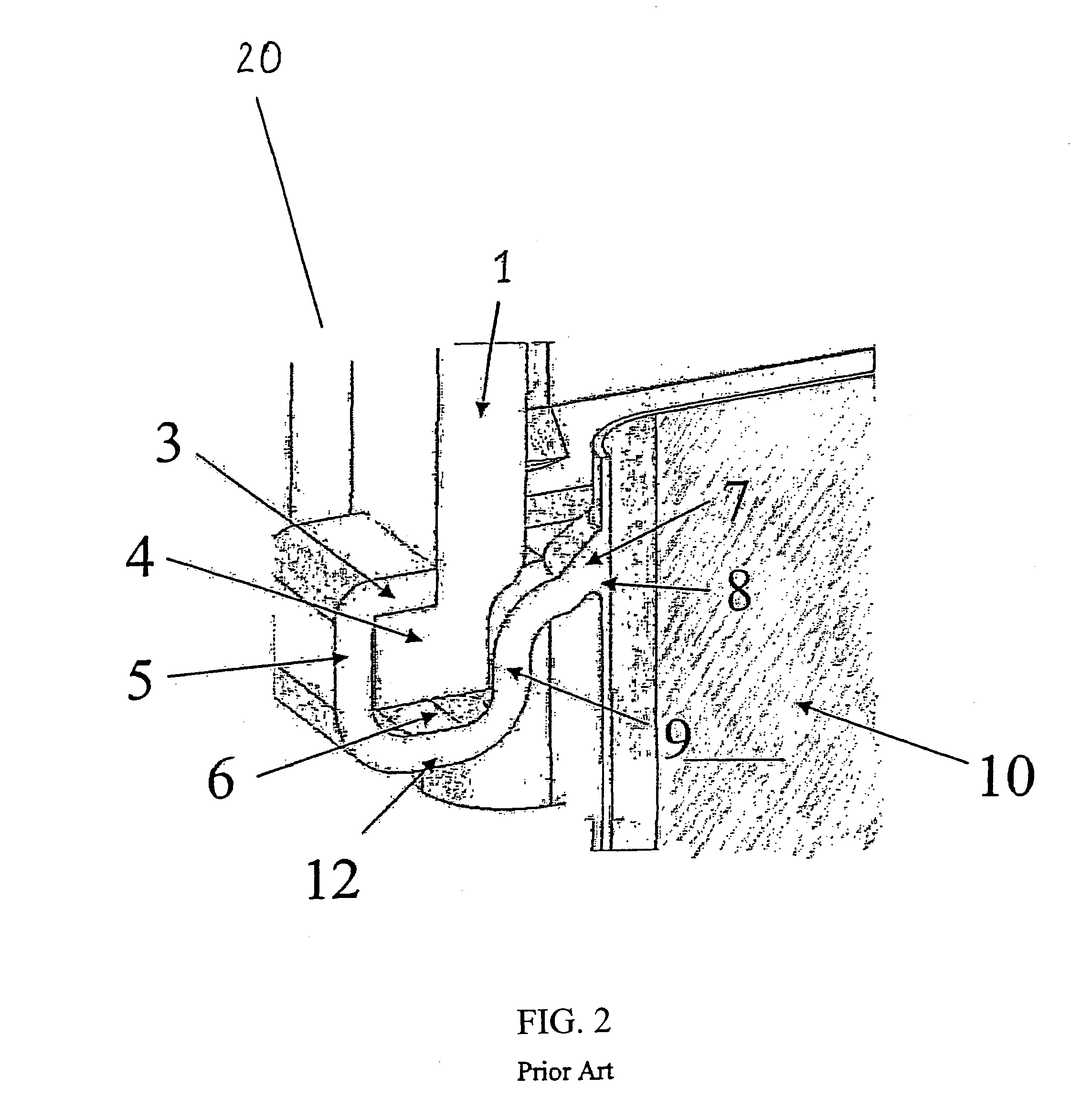
[0034]The present invention, in its preferred embodiments, overcomes many problems of the prior art. In preferred embodiments, the offset of the outer flange is decreased relative to the tube, thus reducing bending moments on the header due to internal pressure loads on the tank. In the preferred embodiments of the present invention, elimination the offset between the gasket sealing surface or gasket (lower) flange and the header plane eliminates a second bending moment, simplifies the header design, reduces material required, and maximizes ambient airflow to the core.

[0035]Elimination of the inner flange and utilization of the tube collar / ferrule ‘collar’ as a rib structure significantly stiffens the header. Linear FEA of preferred embodiments of the present invention indicates up to about a 40% reduction in stress compared to prior art designs examined. The collar also serves to prevent inward translation of the tank foot during crimping. This can improve durability and the header...


PUM


Abstract

The present disclosure relates to automotive heat exchangers, and, heat exchanger tanks with headers. The heat exchanger eliminates the need for use of an inner flange on the header using a collar that also acts as a rib, thereby providing a compact foot plus header tank arrangement with lower stress on the gasket mating surface of the header and tank. The present disclosure also provides a method for providing improved headering for automotive heat exchangers with plastic tanks and headers.

Description

[0001]This application claims priority of provisional application 60 / 530,957 filed Dec. 19, 2003.FIELD OF THE INVENTION[0002]The present invention relates to the field of automotive heat exchangers, and, in particular, to heat exchanger tanks with headers. The present invention further relates to a headering means and a method for providing improved headering means for automotive heat exchangers with plastic tanks and headers, wherein the header inner flange is removed or eliminated.BACKGROUND OF THE INVENTION[0003]Motor vehicles employ heat exchangers to heat or cool various elements of an automotive engine and its component parts. UK Patent application GB 2166862 A, published May 14, 1986, Gebhard Schwarz, ‘Vehicle radiator’ discloses a radiator constituted by flat tubes and a single water containing header with separating webs in the flat tubes which extend in prolongation of the separating wall in the water container. U.S. Pat. No. 4,023,618 issued on May 17, 1977, Kun et al, ‘H...

Claims


Application Information

Patent Timeline
Patent Type & Authority Patents(United States)
IPC IPC(8): F28D1/00B21D51/38F28F9/02F28F9/18
CPCF28F9/0226F28F9/182Y10T29/49389
Inventor POWERS, MICHAEL V.CARAPELLATTI, SCOT
Owner VALEO INC
Why Eureka
Try Eureka