Winding device and method for tearing off web material by planetary-roller

a technology of planetary rollers and winding devices, which is applied in the direction of web handling, thin material handling, article delivery, etc., can solve problems affecting product quality, and achieve the effect of improving product quality and enhancing industrial valu

Active Publication Date: 2012-05-22
CHAN LI MACHINERY
View PDF14 Cites 27 Cited by
  • Summary
  • Abstract
  • Description
  • Claims
  • Application Information

AI Technical Summary

Benefits of technology

[0004]Thus, an objective of the present invention is to provide a winding device with planetary-roller tear-off mechanism in order to improve the quality of web material at the breaking line as tearing off.
[0006]The solution adopted in the present invention allows a web material or a thin web material to be neatly torn off along a pre-formed perforation line without causing any irregular breaking line and the planetary rollers are effectively in tearing off web materials that are tough, whereby the quality of product can be improved and the industrial value is enhanced.

Problems solved by technology

However, using speed difference to break a thin web material may fail for tough web materials since the irregular breaking line may be occurred, which leads to affect the product quality.

Method used


Image

  • Winding device and method for tearing off web material by planetary-roller
  • Winding device and method for tearing off web material by planetary-roller
  • Winding device and method for tearing off web material by planetary-roller

Examples


second embodiment

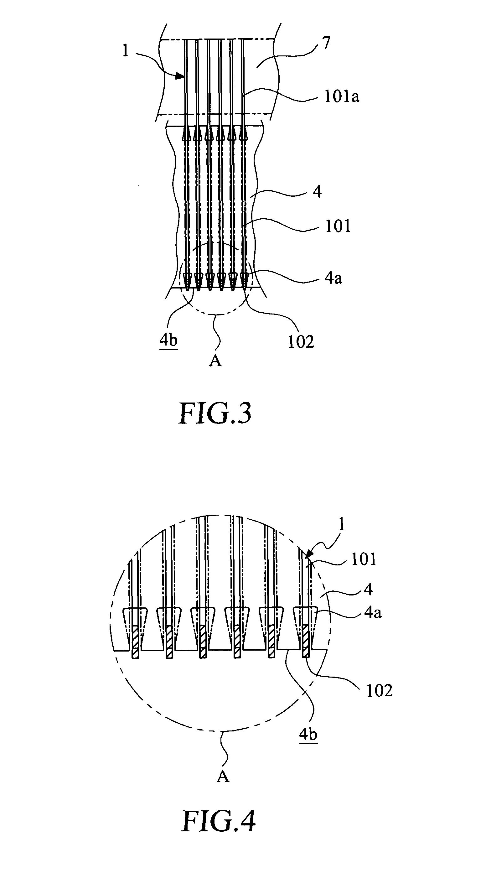
[0044]In a modification of the second embodiment illustrated in FIGS. 16-19, the arms, which are now designated at 201, have circular arc portions 201a that do not form protuberances (the portions referred to by numeral 102 in the previous embodiment) and the circular arc portions 201a of the arms 201 are similarly hidden within the grooves 4a of the first winding roller 4 by a predetermined distance, or are arranged to be substantially flush with the circumferential surface 4b of the first winding roller 4.

first embodiment

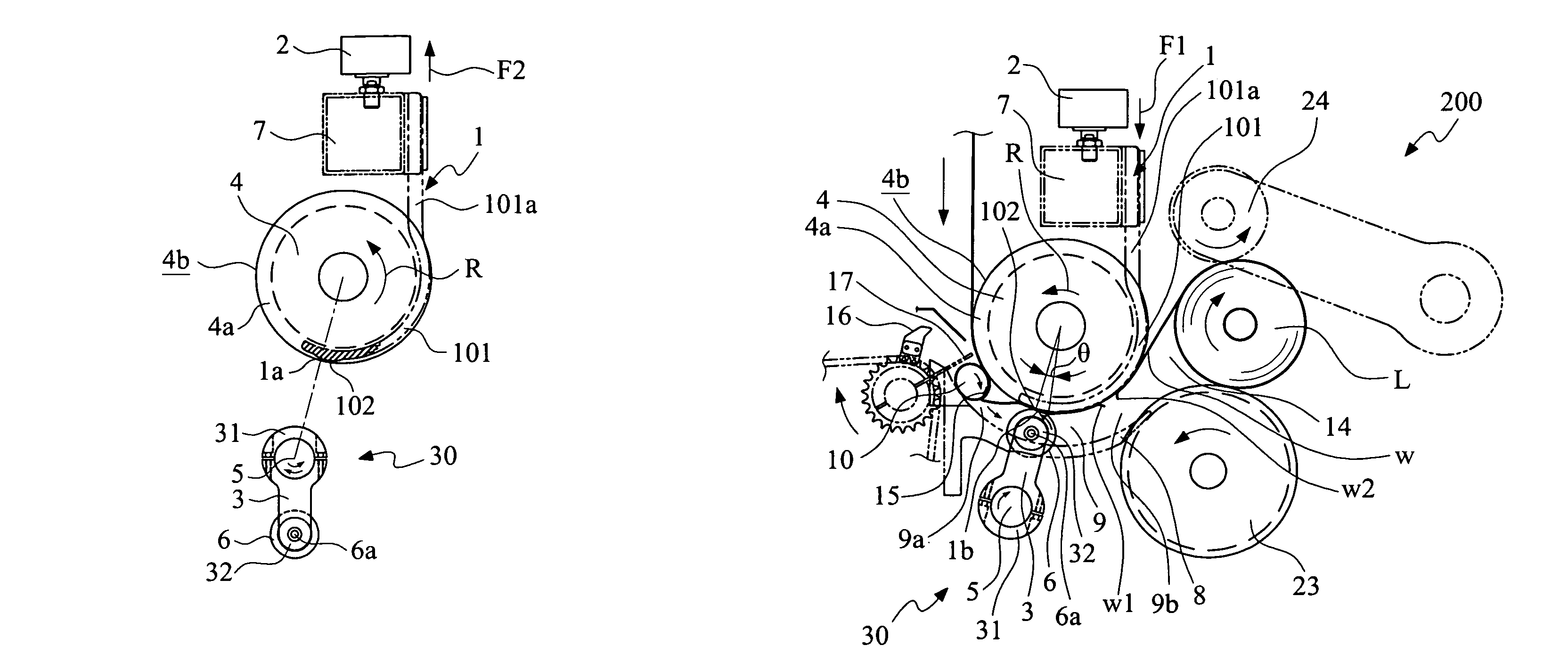
[0045]When the free end 32 of the rotary arm 3 is driven to rotate clockwise to a location facing the circular arc portion 201a of the corresponding arm 201 (see FIG. 20), the web material w is clamped between the ribs 206a of the planetary roller 206 and the circular arc portion 201a of the corresponding arm 201, so that the conveyance of the web material w is temporarily halted. However, on the other hand, the roll L located in the winding zone 14 is continuously rotated, making the web material w subjected to a force acting thereon and thus torn off to form a web material leading edge w1 and a web material trailing edge w2. The planetary roller 206 is a passive rotatable roller and the rotation direction of the rotary arm 3 can be set counterclockwise as desired to meet any practical needs (see FIG. 21) for breaking the web material w. When the tear-off operation of the web material w is carried out by clamping the web material w between the ribs 206a of the planetary roller 206 ...

third embodiment

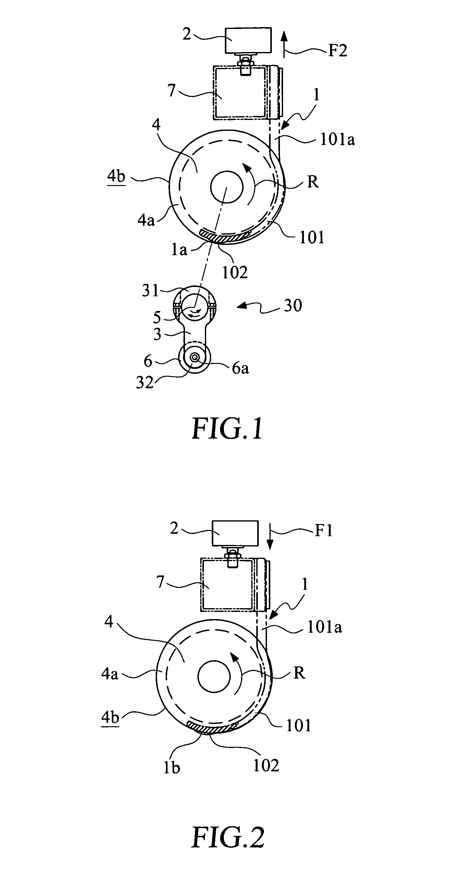
[0048]Referring to FIG. 25, which shows a flowchart of operation corresponding to the third embodiment discussed above, as shown, the first winding roller 4 is driven to rotate in a predetermined direction R (Step 401). A web material w is driven by the first winding roller 4 to the inlet end 9a of the curved channel 9 and the outlet end 9b of the curved channel 9 to reach the winding zone 14 where the web material w is wound to form a roll L (Step 402). When the winding of the roll L is about to complete, the rotary arm 3 is driven to rotate (Step 303) so that when the free end 32 of the rotary arm 3 is driven to rotate to a position facing the circumferential surface 4b of the first winding roller 4, the web material w is subjected to clamping by the circumferential surface 4b of the first winding roller 4 and the planetary roller 6 (Step 404). At the time period when the web material w is clamped between the circumferential surface 4b of the first winding roller 4 and the planeta...


PUM


Abstract

A winding device with a planetary-roller tear-off mechanism is disclosed, comprising a first winding roller which is driven to rotate in a predetermined direction and a plurality of core support plates that are arranged at a predetermined distance below the first winding roller, wherein an interval between the core support plates and the first winding roller is defined as a curved channel. A web material is conveyed through the curved channel to a winding zone to be wound as a roll. The planetary-roller tear-off mechanism includes a plurality of rotary arms and a plurality of planetary rollers. Each rotary arm is set at a predetermined location below the first winding roller, and having a driving end and a free end. Each planetary roller is rotatable, and mounted to the free end of the respective rotary arm. When the free end of the rotary arm is driven to rotate to a position facing a circumferential surface of the first winding roller, the web material is subjected to a drag force acting thereon to break the web material.

Description

FIELD OF THE INVENTION[0001]The present invention relates to a winding device, and in particular to a winding device having a planetary-roller tear-off mechanism and a method for tearing off a web material.BACKGROUND OF THE INVENTION[0002]A conventional core used in a winding device is forwarded into a curved channel through the conveyance of a conveyor and a push plate in order to be transported to a winding zone in which a thin web material is wound on the core to form a roll, such as a toilet tissue roll and a kitchen towel roll. After the roll is completed, a cutter is employed to cut the thin web material or the rotational speed of a rotary bar is controlled to have a relative speed thereof with respect to a first winding roller or a second winding roller slower so as to induce a speed difference, which breaks or tears off the thin web material.SUMMARY OF THE INVENTION[0003]However, using speed difference to break a thin web material may fail for tough web materials since the i...

Claims


Application Information

Patent Timeline
Patent Type & Authority Patents(United States)
IPC IPC(8): B65H35/10
CPCB65H19/2269B65H19/267B65H2403/942
Inventor TSAI, TUNG-I
Owner CHAN LI MACHINERY
Why Eureka
Try Eureka