
Hydraulic control apparatus for automatic transmission

a technology of automatic transmission and control apparatus, which is applied in the direction of gearing control, gearing elements, gearing, etc., can solve the problems of increasing the size of automatic transmissions and affecting the implementation of compact automatic transmissions, and achieves the effect of low shift speed and low shift speed

Active Publication Date: 2012-05-22
AISIN AW CO LTD
View PDF11 Cites 13 Cited by
  • Summary
  • Abstract
  • Description
  • Claims
  • Application Information

AI Technical Summary

Benefits of technology

[0007]However, such a structure in which the failsafe mode is attained by reversely inputting an oil pressure to the solenoid valves has a complex oil passage structure, thereby hindering implementation of compact automatic transmissions.
[0008]Especially, in hydraulic control apparatuses for automatic transmissions that achieve only the seventh forward speed in the failure-safe state, such as that of Japanese Patent Application Publication No. JP-A-2007-177932, vehicles having high engine power, for example, withstand starting and low-speed traveling even at the seventh forward speed. However, in vehicles, which have low engine power, and thus, may have an engine stop upon starting or during low-speed traveling if it attains only a high shift speed, it is preferable to be able to attain a low shift speed or a high shift speed in the failure-safe state, according to the traveling state of the vehicles. However, in order to attain a different shift speed in the failure-safe state by the reverse input as described above, a more complex oil passage structure is required, thereby increasing the size of the automatic transmissions.
[0009]Thus, it is an object of the present invention to provide a hydraulic control apparatus for an automatic transmission, in which solenoid valves for supplying a working fluid pressure to hydraulic servos of friction engagement elements are formed by normally closed type solenoid valves, and one of a low shift speed and a high shift speed can be achieved even in case of all-solenoids-off failure.
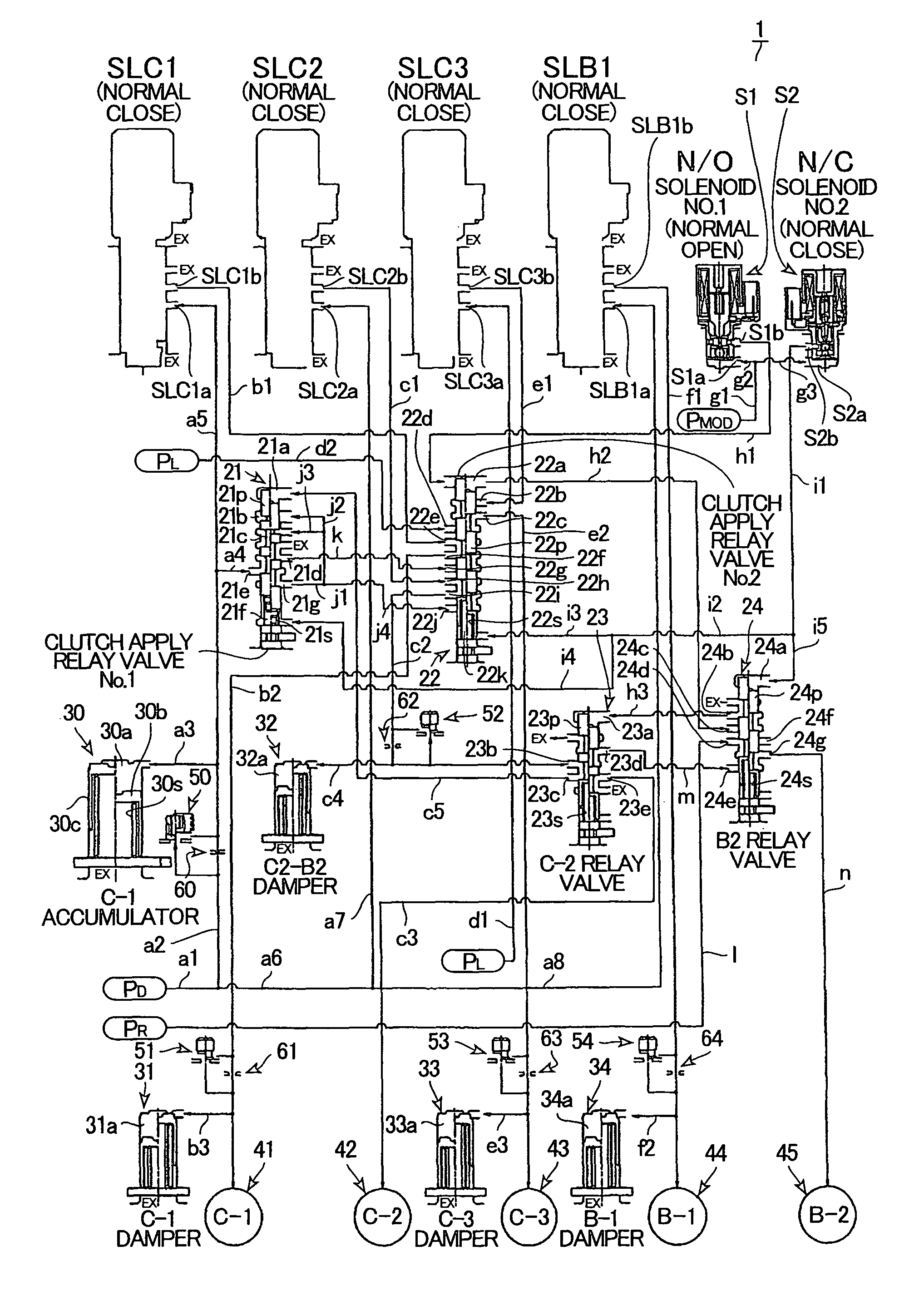
[0015]According to the aspect of the present invention, the preliminary shift speed switch valve is switched between the lower shift speed-side position where the first preliminary oil pressure for the hydraulic servo of the first friction engagement element is output, and the higher shift speed-side position where the second preliminary oil pressure for the hydraulic servo of the second friction engagement element is output, based on the engagement state of the second friction engagement element, and the oil pressure supply switch valve is switched between the normal-state position where the first, second, and third working fluid pressures can be supplied to the hydraulic servos of the first, second, and third friction engagement elements, respectively, and the failure-state position where the first and second preliminary oil pressures can be supplied to the hydraulic servos of the first and second friction engagement elements, respectively, and the line pressure can be supplied to the hydraulic servo of the third friction engagement element, during a failure that causes de-energization. Thus, the first, second, and third solenoid valves can be formed by normally closed type solenoid valves to reduce power consumption. Thus, one of a low shift speed and a high shift speed can be attained in case of a failure that causes the de-generated state, without complicating the oil passage structure, while enabling fuel economy of a vehicle to be improved. Thus, the failure-safe function can be enhanced.
[0018]Also, in the hydraulic control apparatus according to the aspect of the present invention, when a vehicle is restarted upon a failure that causes de-energization, the preliminary shift speed switch valve is switched to the lower shift speed-side position, based on the biasing force of the second biasing means, and the oil pressure supply switch valve is switched to the failure-state position, whereby the first preliminary oil pressure is supplied to the hydraulic servo of the first friction engagement element. Thus, a low shift speed is attained, enabling restarting of the vehicle.
[0019]Further, in the hydraulic control apparatus according to the aspect of the present invention, the preliminary shift speed switch valve receives the forward range pressure as a source pressure of the first and second preliminary oil pressures. Thus, in the case of restarting the vehicle upon a failure that causes de-energization, the range switch valve is switched to other range to discharge the forward range pressure, and then, is switched back to the forward range to supply the first preliminary oil pressure to the hydraulic servo of the first friction engagement element, whereby a low shift speed is attained, enabling restarting of the vehicle. This can eliminate the need for a separate operation, such as temporarily stopping the engine, when, e.g., restarting the vehicle in case of a failure that causes de-energization.

Problems solved by technology

However, such a structure in which the failsafe mode is attained by reversely inputting an oil pressure to the solenoid valves has a complex oil passage structure, thereby hindering implementation of compact automatic transmissions.
However, in order to attain a different shift speed in the failure-safe state by the reverse input as described above, a more complex oil passage structure is required, thereby increasing the size of the automatic transmissions.

Method used


Image

  • Hydraulic control apparatus for automatic transmission
  • Hydraulic control apparatus for automatic transmission
  • Hydraulic control apparatus for automatic transmission

Examples


Embodiment Construction

[0024]Hereinafter, an embodiment of the present invention will be described with reference to FIGS. 1 through 4.

[0025][Schematic Structure of Automatic Transmission]

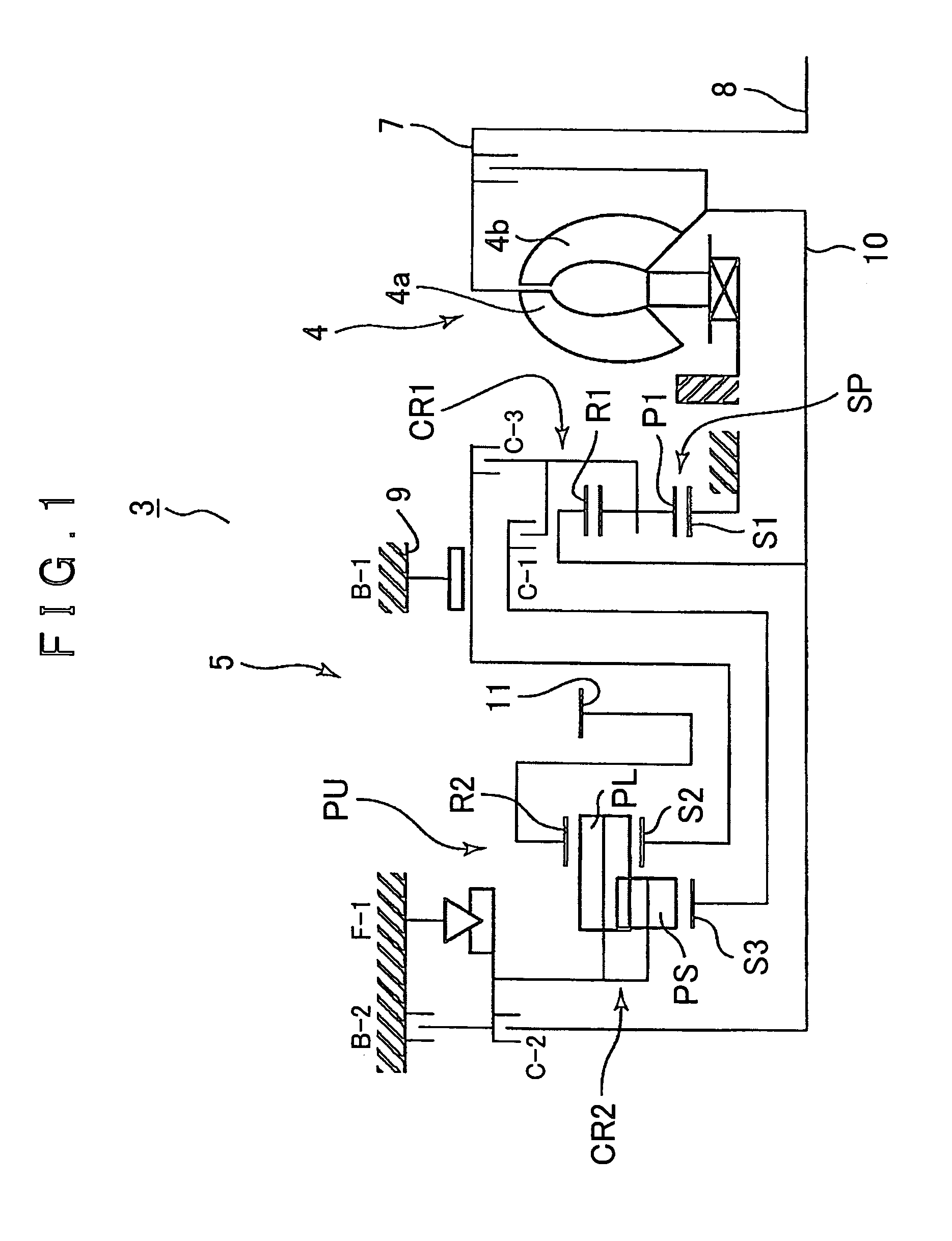
[0026]First, a schematic structure of an automatic transmission 3 to which the present invention can be applied will be described with reference to FIG. 1. As shown in FIG. 1, the automatic transmission 3, which is preferably used in, e.g., FF type (front engine, front drive) vehicles, has an input shaft 8 of the automatic transmission 3, which can be connected to an engine (not shown), and includes a torque converter 4 and an automatic speed change mechanism 5, which are disposed about an axial direction of the input shaft 8.

[0027]The torque converter 4 has a pump impeller 4a connected to the input shaft 8 of the automatic transmission 3, and a turbine runner 4b to which rotation of the pump impeller 4a is transmitted via a working fluid. The turbine runner 4b is connected to an input shaft 10 of the automatic speed cha...


PUM


Abstract

A hydraulic control apparatus for an automatic transmission includes a first solenoid valve, a second solenoid valve, a third solenoid valve, a preliminary shift speed switch valve, and an oil pressure supply switch valve, which is switched between a normal-state position where the first, second, and third working fluid pressures can be supplied to the hydraulic servos of the first, second, and third friction engagement elements, respectively, and a failure-state position where the first and second preliminary oil pressures can be supplied to the hydraulic servos of the first and second friction engagement elements, respectively, and a line pressure can be supplied to the hydraulic servo of the third friction engagement element, during a failure that causes de-energization.

Description

INCORPORATION BY REFERENCE[0001]The disclosure of Japanese Patent Application No. 2008-255095 filed on Sep. 30, 2008 including the specification, drawings and abstract is incorporated herein by reference in its entirety.BACKGROUND OF THE INVENTION[0002]The present invention generally relates to hydraulic control apparatuses for automatic transmissions that are mounted on vehicles and the like. More particularly, the present invention relates to hydraulic control apparatuses for automatic transmissions, which enable a shift speed to be attained even in case of a failure that causes de-energization.[0003]In general, in multi-stage automatic transmissions that are mounted on vehicles and the like, each shift speed is formed by controlling the rotating state of each rotary element of a speed change gear mechanism according to the engagement state of a plurality of friction engagement elements. The engagement state of the plurality of friction engagement elements is controlled by electri...

Claims


Application Information

Patent Timeline
Patent Type & Authority Patents(United States)
IPC IPC(8): F16H61/26F16H31/00
CPCF16H61/0206F16H61/12F16H61/686Y10T477/69363F16H2061/1268Y10S477/906Y10T477/6936F16H2061/1232
Inventor SHIMIZU, TETSUYATSUCHIDA, KENICHISUZUKI, AKITOMOISHIKAWA, KAZUNORI
Owner AISIN AW CO LTD
Learn More