Flexible imaging fiber bundle monitoring system for combustion turbines

a technology of flexible imaging and bundle monitoring, which is applied in the direction of television systems, combustion types, instruments, etc., can solve the problems of general restrictions on the monitoring of components of turbine engines by continuous monitoring systems, and problems such as identification of problems

Active Publication Date: 2012-05-22
SIEMENS ENERGY INC
View PDF21 Cites 37 Cited by
  • Summary
  • Abstract
  • Description
  • Claims
  • Application Information

AI Technical Summary

Problems solved by technology

For example, problems may be identified through visual inspection by use of a borescope, such as during routine downtime maintenance of the gas turbine engine.
Accordingly, monitoring of components in turbine engines by continuous monitoring systems has generally been restricted to those locations that present substantially unobstructed access between the outer casing wall and the interior portion of the engine.

Method used


Image

  • Flexible imaging fiber bundle monitoring system for combustion turbines
  • Flexible imaging fiber bundle monitoring system for combustion turbines
  • Flexible imaging fiber bundle monitoring system for combustion turbines

Examples


Embodiment Construction

[0027]In the following detailed description of the preferred embodiment, reference is made to the accompanying drawings that form a part hereof, and in which is shown by way of illustration, and not by way of limitation, a specific preferred embodiment in which the invention may be practiced. It is to be understood that other embodiments may be utilized and that changes may be made without departing from the spirit and scope of the present invention.

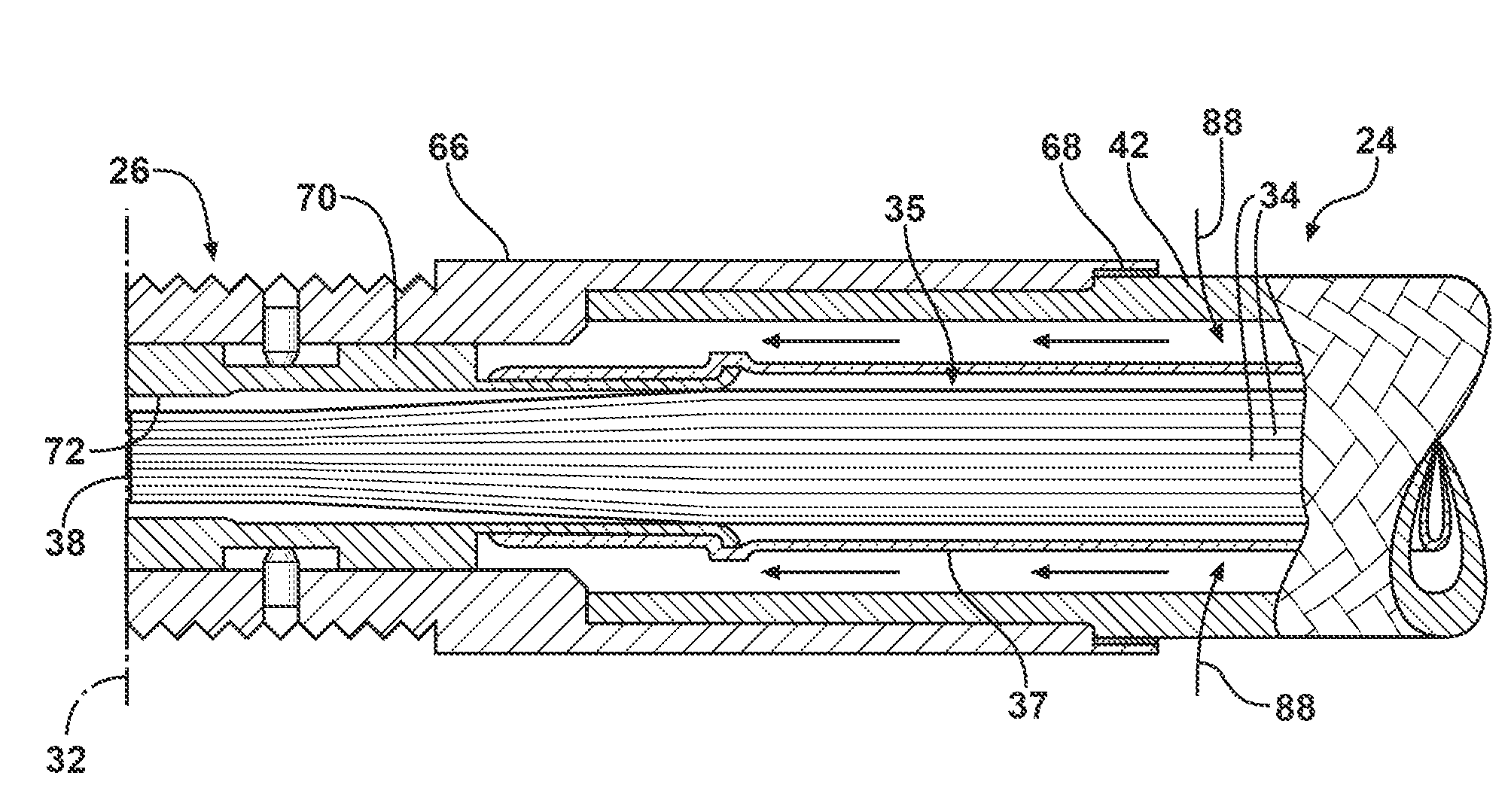
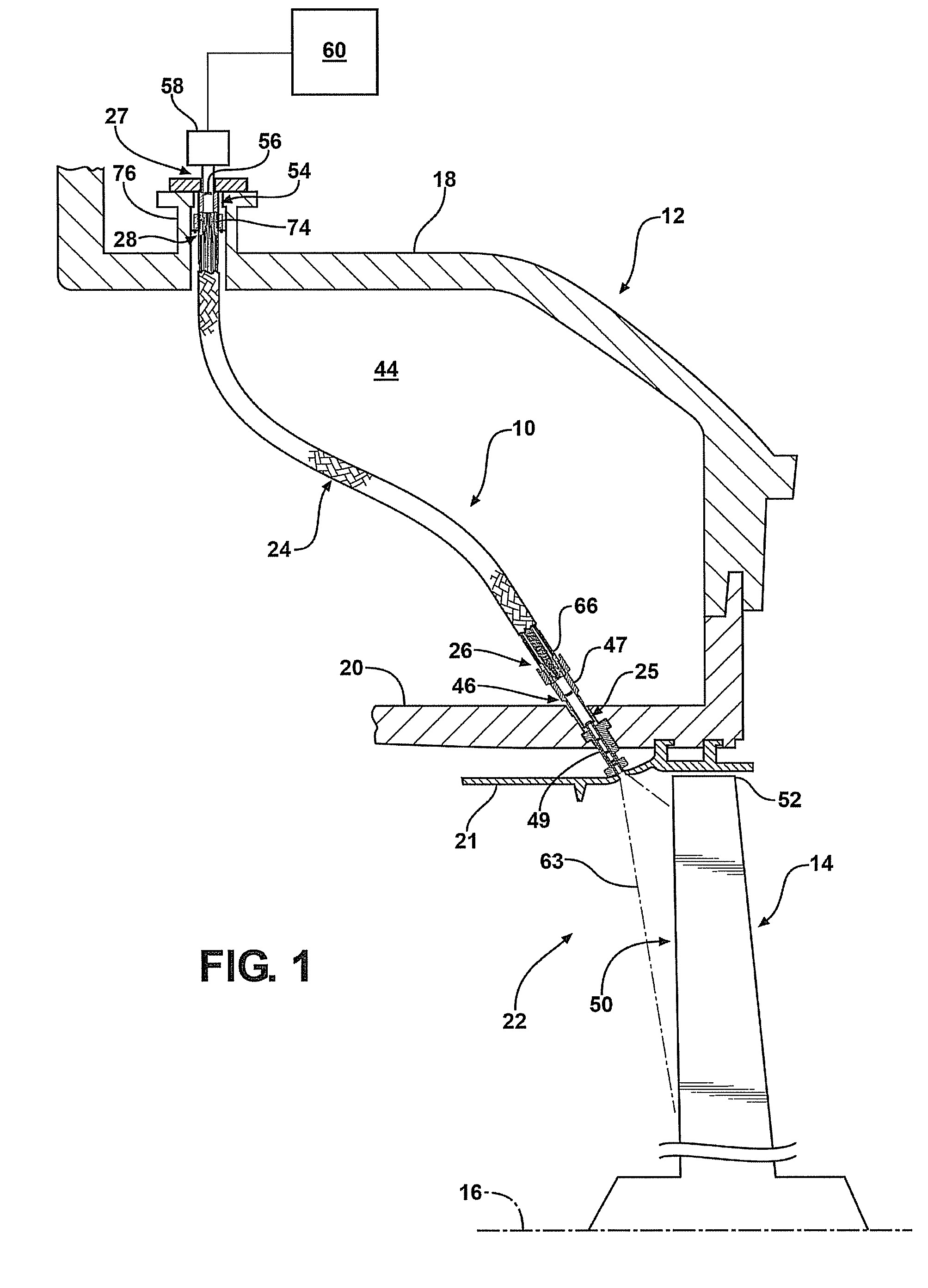
[0028]Referring initially to FIG. 1, an imaging system 10 is illustrated for providing imaging of a component in a gas turbine engine 12 during operation of the turbine engine 12. In particular, the imaging system 10 is shown mounted to the turbine engine 12 and positioned extending between an outer casing wall 18 and a blade ring structure 20 supported radially inwardly from the outer casing wall 18 in a turbine section of the turbine engine 12. In the illustrated embodiment, the imaging system 10 is provided for imaging a location on a...


PUM


Abstract

An imaging system for on-line imaging of a component in a gas turbine engine. The imaging system includes a flexible imaging bundle formed by a plurality of optical elements. An imaging end of the optical elements images a component in a hot gas path of the engine during operation of the engine and a viewing end provides an image of the component at a location displaced from the hot gas path. The optical elements are surrounded by a flexible metal sheath that is permeable to air to provide cooling air the optical elements from an air source surrounding the flexible imaging bundle.

Description

FIELD OF THE INVENTION[0001]The present invention relates to a device for monitoring a turbine engine component and, more particularly, to a device for imaging a location on a turbine blade in a hot gas path during operation of a gas turbine engine.BACKGROUND OF THE INVENTION[0002]Inaccessible or confined areas such as, for example, the interior parts of gas turbine engines, often require routine inspection to verify the integrity of internal engine parts and maintain safe operation of the engine by identifying potential problems, i.e., defects in a part, prior to failure of the part, or to identify the source of an existing problem. For example, problems may be identified through visual inspection by use of a borescope, such as during routine downtime maintenance of the gas turbine engine.[0003]Additional monitoring of the turbine engine may be performed during operation of the engine to further identify the condition of components located within the hot gas path of the engine. Whi...

Claims


Application Information

Patent Timeline
Patent Type & Authority Patents(United States)
IPC IPC(8): H04N7/18
CPCF01D21/003G02B23/26G02B23/2492G02B23/2484G01K1/026
Inventor ZOMBO, PAUL J.JONNALAGADDA, VINAYBALEINE, ERWAN
Owner SIEMENS ENERGY INC
Why Eureka
Try Eureka