
Method of transmitting feedback data in a multiple antenna system

a feedback data and multiple antenna technology, applied in the field of wireless communication, can solve problems such as significant overhead

Active Publication Date: 2012-05-22
LG ELECTRONICS INC
View PDF20 Cites 35 Cited by
  • Summary
  • Abstract
  • Description
  • Claims
  • Application Information

AI Technical Summary

Benefits of technology

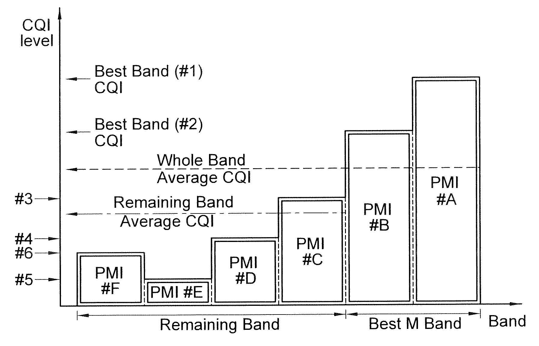
The present invention provides a method for transmitting feedback data in a multiple antenna system. The method involves receiving a request message of feedback data on a downlink channel, selecting a set of subbands within a plurality of subbands, and generating the feedback data comprising a frequency selective PMI, a frequency flat PMI, a best band CQI, and a whole band CQI. The feedback data is then transmitted on an uplink channel allocated to the uplink scheduling information or on a shared uplink channel. The technical effect of this invention is to improve the efficiency and accuracy of feedback data transmission in a multiple antenna system.

Problems solved by technology

However, a significantly large overhead is caused when the CQIs and PMIs for all subbands are transmitted with limited radio resources.

Method used


Image

  • Method of transmitting feedback data in a multiple antenna system
  • Method of transmitting feedback data in a multiple antenna system
  • Method of transmitting feedback data in a multiple antenna system

Examples


Embodiment Construction

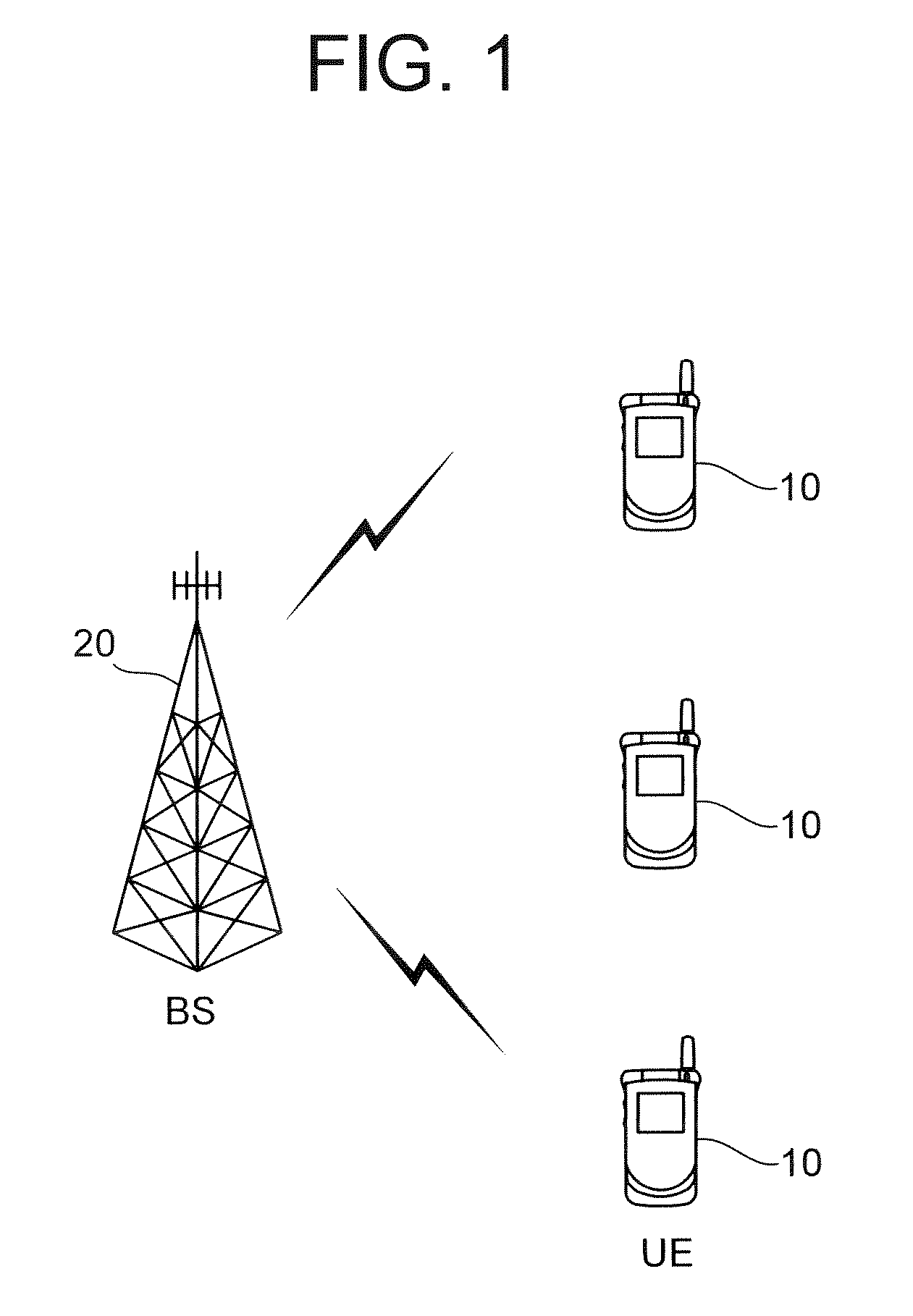
[0046]FIG. 1 shows a wireless communication system. The wireless communication system can be widely deployed to provide a variety of communication services, such as voices, packet data, etc.

[0047]Referring to FIG. 1, the wireless communication system includes at least one user equipment (UE) 10 and a base station (BS) 20. The UE 10 may be fixed or mobile, and may be referred to as another terminology, such as a mobile station (MS), a user terminal (UT), a subscriber station (SS), a wireless device, etc. The BS 20 is generally a fixed station that communicates with the UE 10 and may be referred to as another terminology, such as a node-B, a base transceiver system (BTS), an access point, etc. There are one or more cells within the coverage of the BS 20.

[0048]There is no restriction on a multiple access scheme used in the wireless communication system. The multiple access scheme may be based on code division multiple access (CDMA), time division multiple access (TDMA), frequency divis...


PUM


Abstract

A method of transmitting feedback data in a multiple antenna system comprises receiving a request message of feedback data on a downlink channel, the request message comprising uplink scheduling information, selecting a set of M (M≧1) subbands within a plurality of subbands, generating the feedback data, the feedback data comprising a frequency selective PMI (preceding matrix indicator), a frequency flat PMI, a best band CQI (channel quality indicator) and a whole band CQI, and transmitting the feedback data on a uplink channel allocated to the uplink scheduling information.

Description

CROSS-REFERENCE TO RELATED APPLICATIONS[0001]This application claims the benefit of priority of U.S. Provisional application Ser. No. 60 / 978,140 filed on Oct. 8, 2007, U.S. Provisional application Ser. No. 61 / 025,304 filed on Feb. 1, 2008, Korean Patent Application No. 10-2007-0080519 filed on Aug. 10, 2007, Korean Patent Application No. 10-2007-0081913 filed on Aug. 14, 2007, Korean Patent Application No. 10-2007-0118168 filed on Nov. 19, 2007, Korean Patent Application No. 10-2008-0005864 filed on Jan. 18, 2008, and Korean Patent Application No. 10-2008-0073340 filed on Jul. 28, 2008 which are incorporated by reference in its entirety herein.BACKGROUND[0002]1. Technical Field[0003]The present invention relates to wireless communications, and more particularly, to a method for transmitting feedback data in a multiple antenna system.[0004]2. Related Art[0005]Wireless communication systems are widely used to provide various types of communications. For example, voice and / or data are ...

Claims


Application Information

Patent Timeline
Patent Type & Authority Patents(United States)
IPC IPC(8): G01R31/08H04L12/26H04J1/16H04J3/14H04L1/00G08C15/00G06F11/00
CPCH04B7/0417H04B7/0626H04B7/0639H04B7/066H04L5/0053H04L5/0057H04L25/03343H04L2025/03426H04L5/0023H04B7/0621H04B7/0623H04B7/063H04B7/0632H04B7/0658H04W72/21
Inventor KO, HYUN SOOIHM, BIN CHULCHUN, JIN YOUNGLEE, WOOK BONGLEE, MOON IL
Owner LG ELECTRONICS INC
Learn More