System to enhance and control the pressurization, operating pressures, and flushing of drip dispersal systems

a drip dispersal system and operating pressure technology, applied in water cleaning, sedimentation settling tanks, separation processes, etc., can solve the problems of inability to meet rigid design parameters, inability to properly function emitters, damage to tubing and connections,

Active Publication Date: 2012-05-29
SVETLIK III RUDY JAMES
View PDF9 Cites 3 Cited by
  • Summary
  • Abstract
  • Description
  • Claims
  • Application Information

AI Technical Summary

Benefits of technology

[0007]When the minimum operating pressure is reached, the blow out valve opens and allows all flow above what is required to maintain minimum field operating pressure to bypass to the source tank or location of choice. Advantageously, this ensures that the emitters can function as designed while allowing all excess flow to be used continuously to flush the tubing. The blow-out valve closes at pressures near and / or below minimum field operating pressure, such that will quick pressurization of the drip tubing at the beginning of the dosing cycle is ensured. This feature advantageously also serves as a back-pressure regulator to regulate field pressure from the return end of system flow rather than from the source, such that the system is not adversely affected by pressure changes at the pump end of the system.

Problems solved by technology

If the pressure is too high, the tubing and connections can be damaged and, if the pressure is low, the emitters will not function properly.
The effluent pressure in the tubing is currently regulated by one of a number of methods, each of which presents its own problems.
However, rigid design parameters are sometimes difficult to meet during installation of system due to actual field conditions.
In this case the pressure regulator regulates pressure by restricting flow, which does not allow the excess flow to be used for cleaning the tubing through a continuous flushing action.
Here, if pump or filter conditions cause pressure fluctuation then the operation of the manually operated ball-valve setting becomes incorrect and creates either high- or low-pressure situations.

Method used


Image

  • System to enhance and control the pressurization, operating pressures, and flushing of drip dispersal systems
  • System to enhance and control the pressurization, operating pressures, and flushing of drip dispersal systems

Examples


Embodiment Construction

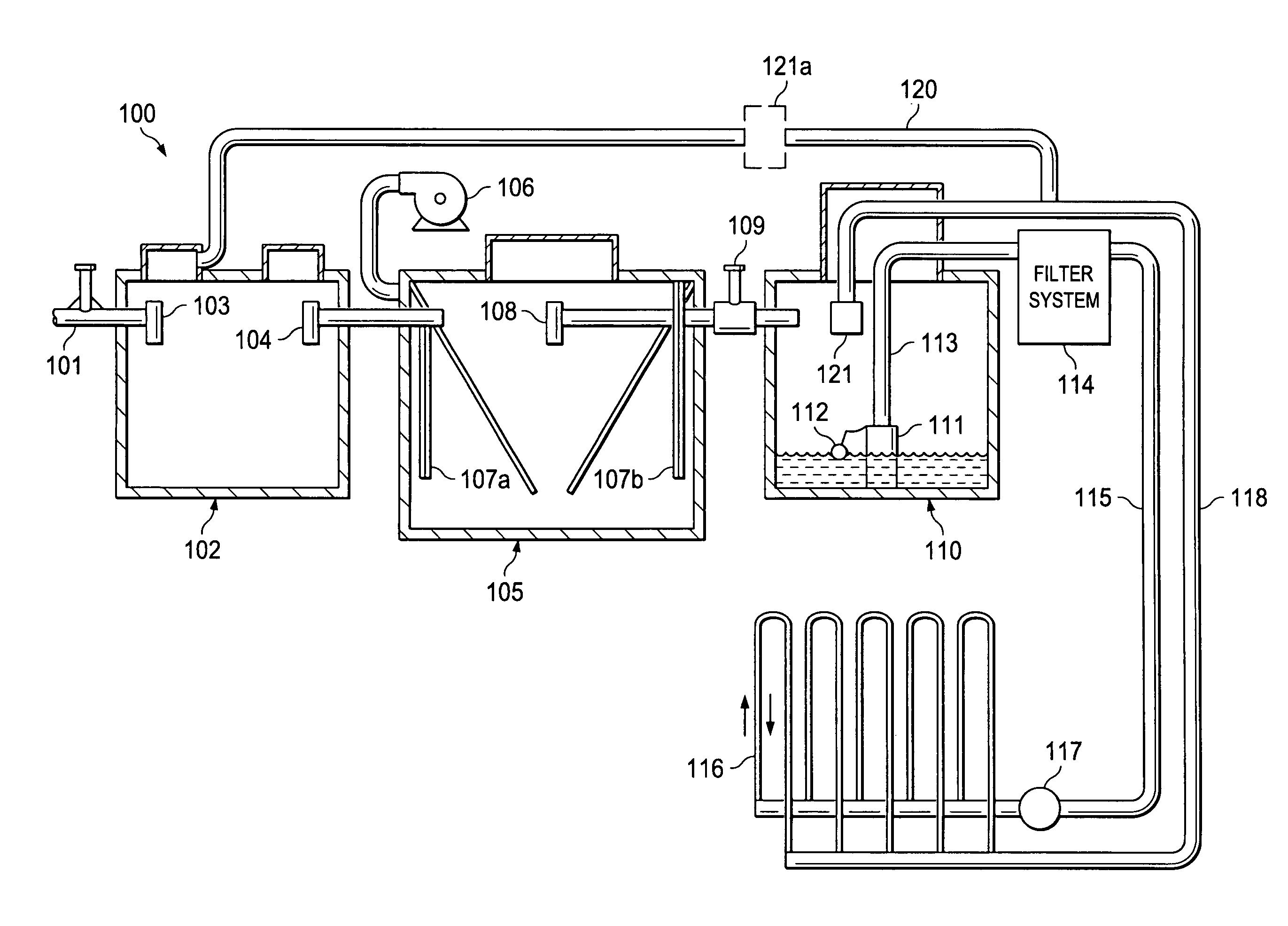
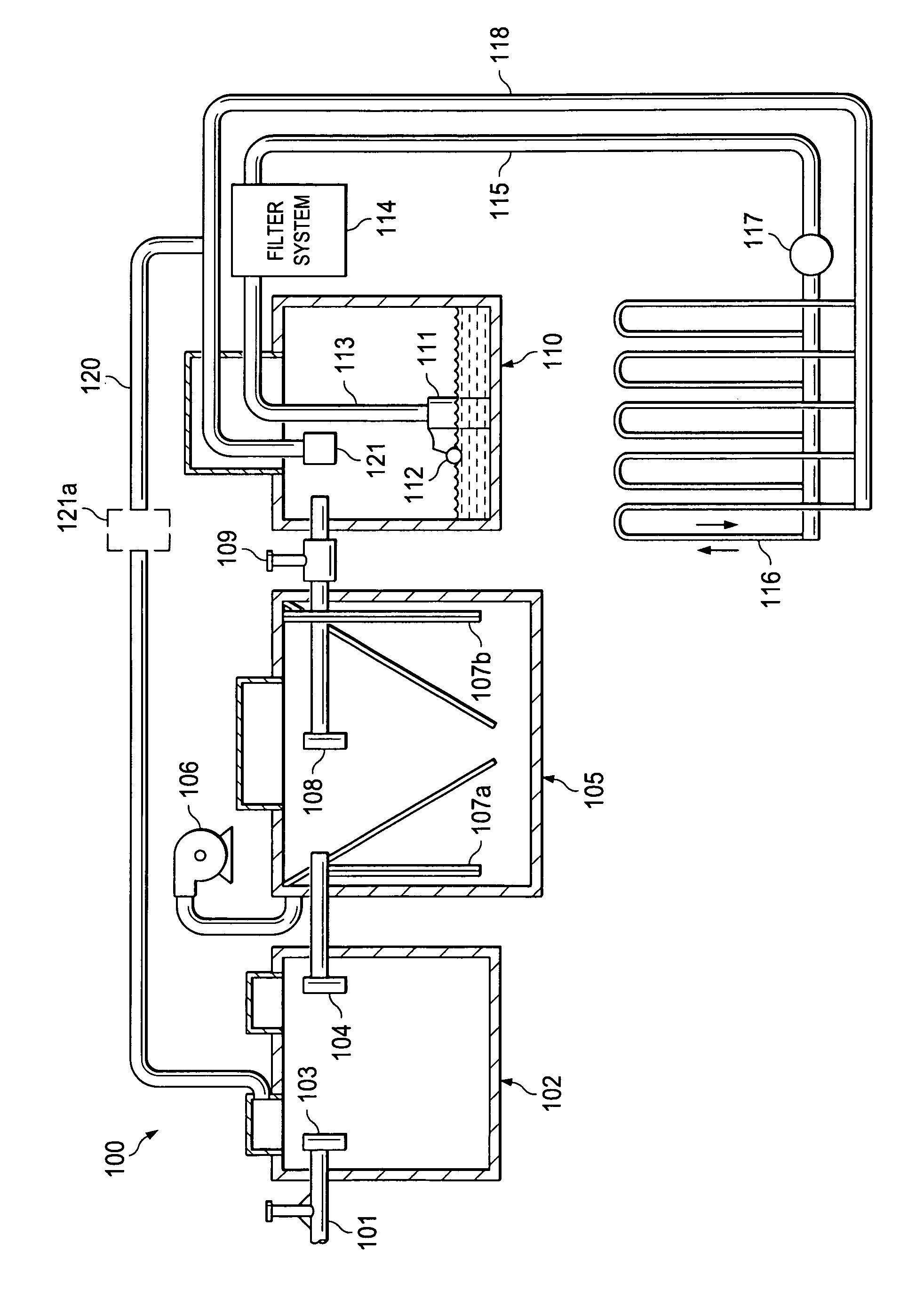
[0010]The principles of the present invention and their advantages are best understood by referring to the illustrated embodiment depicted in FIG. 1 of the drawings, in which like numbers designate like parts.

[0011]FIG. 1 is a diagram of an exemplary septic / waste water recovery system 100 suitable for describing one particular application of the principles of the present invention, although these principles can be applied to a wide range of other fluid filtering systems.

[0012]As shown in FIG. 1A, system 100 includes an effluent input line 101, which receives effluent from the drains of a house or small commercial concern. This effluent enters a trash tank 102 through trash tank inlet 103. Generally, the effluent remains in trash tank 102 while organic solids settle-out. After settling, the remaining liquid effluent in trash tank 102 is transferred through outlet 104 and inlet 107, using either pumping or gravity flow, into aerobic tank 105, where a pump 106 pumps air into the efflue...


PUM

PropertyMeasurementUnit
areaaaaaaaaaaa
pressureaaaaaaaaaa
operating pressuresaaaaaaaaaa

Abstract

A drip disposal system includes a fluid source including a pump for cyclically pumping fluid from the fluid source, a set of drip field lines connected to the fluid source for dispersing at least some fluid provided by the source across an area of ground, and a return line for returning fluid not dispersed by the set of drip field lines to the fluid source. A blow-out valve is connected to the return line for controlling fluid flow through the return line during each cycle, the blow-out valve opening when a pressure of the fluid flowing through the return line exceeds a selected minimum pressure and closing when the pressure of the fluid flowing through the return line goes below the selected minimum pressure.

Description

CROSS-REFERENCE TO RELATED DATA[0001]This application claims the benefit of U.S. Provisional Application No. 61 / 072,444 filed Mar. 31, 2008.FIELD OF INVENTION[0002]The present invention relates in general to septic / waste water recovery techniques, and in particular, to a system to enhance and control the pressurization, operating pressures, and flushing of drip dispersal systems.BACKGROUND OF INVENTION[0003]Wastewater drip dispersal systems utilize tubing with small drip emitters to disperse wastewater into the soil. The emitters operate properly within a defined pressure range. If the pressure is too high, the tubing and connections can be damaged and, if the pressure is low, the emitters will not function properly. The effluent pressure in the tubing is currently regulated by one of a number of methods, each of which presents its own problems.[0004]In one method, the effluent pressure in the tubing is regulated by utilizing rigid design parameters. However, rigid design parameters...

Claims


Application Information

Patent Timeline
Patent Type & Authority Patents(United States)
IPC IPC(8): C02F3/30C02F1/00
CPCC02F3/288C02F3/006C02F1/76C02F3/02C02F2209/03C02F2209/42C02F2209/44Y02W10/10
Inventor SVETLIK, III, RUDY JAMES
Owner SVETLIK III RUDY JAMES
Why Eureka
Try Eureka