
Portable cutting table and associated method

a cutting table and portability technology, applied in the field of cutting tables, can solve the problems of unnecessary dulling of the knife when the object is in the object, dangerous slipping and injury, and increased force for dulling of the cutlery

Active Publication Date: 2012-06-05
IYEWARUN ABAYOMI
View PDF11 Cites 3 Cited by
  • Summary
  • Abstract
  • Description
  • Claims
  • Application Information

AI Technical Summary

Benefits of technology

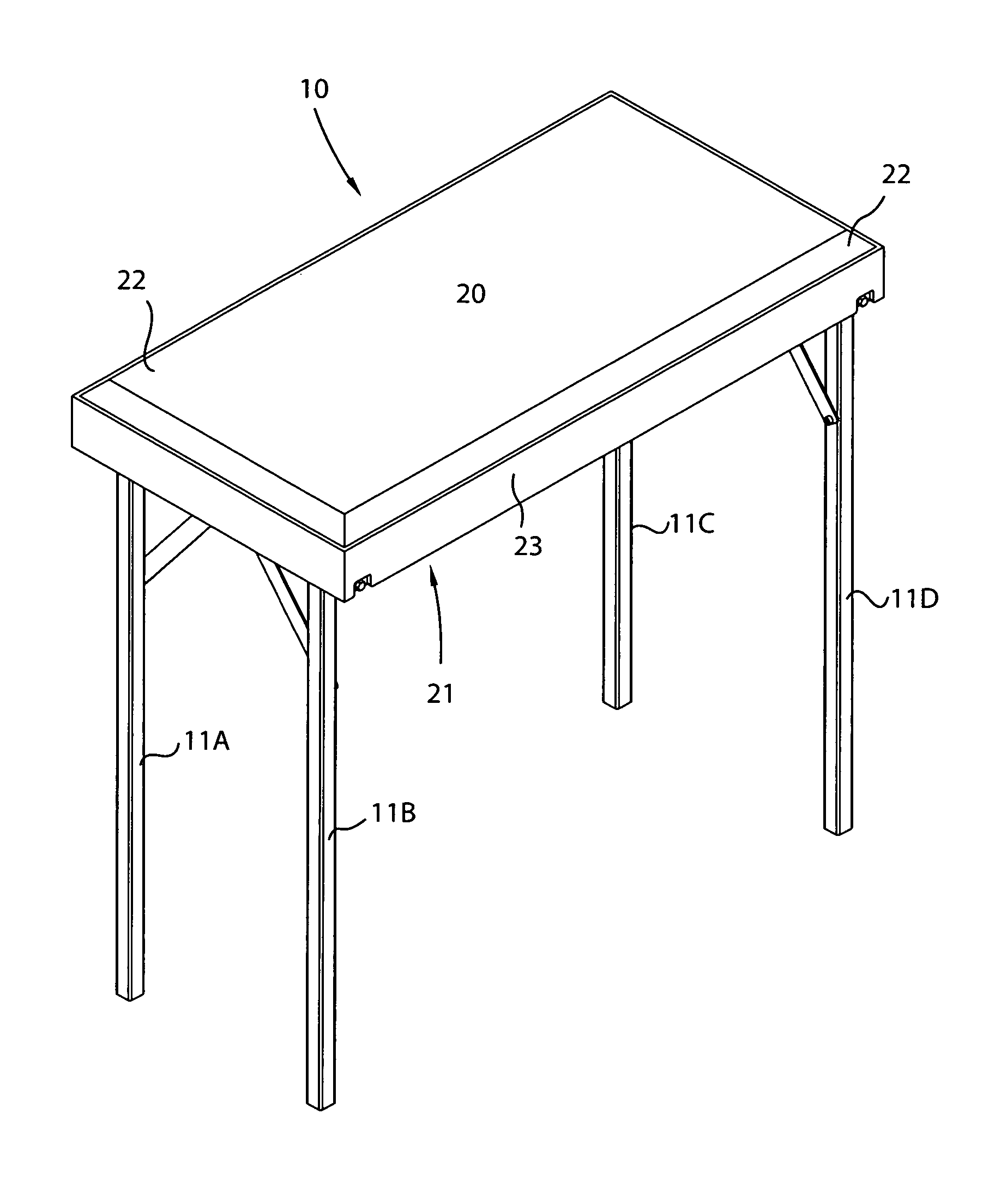
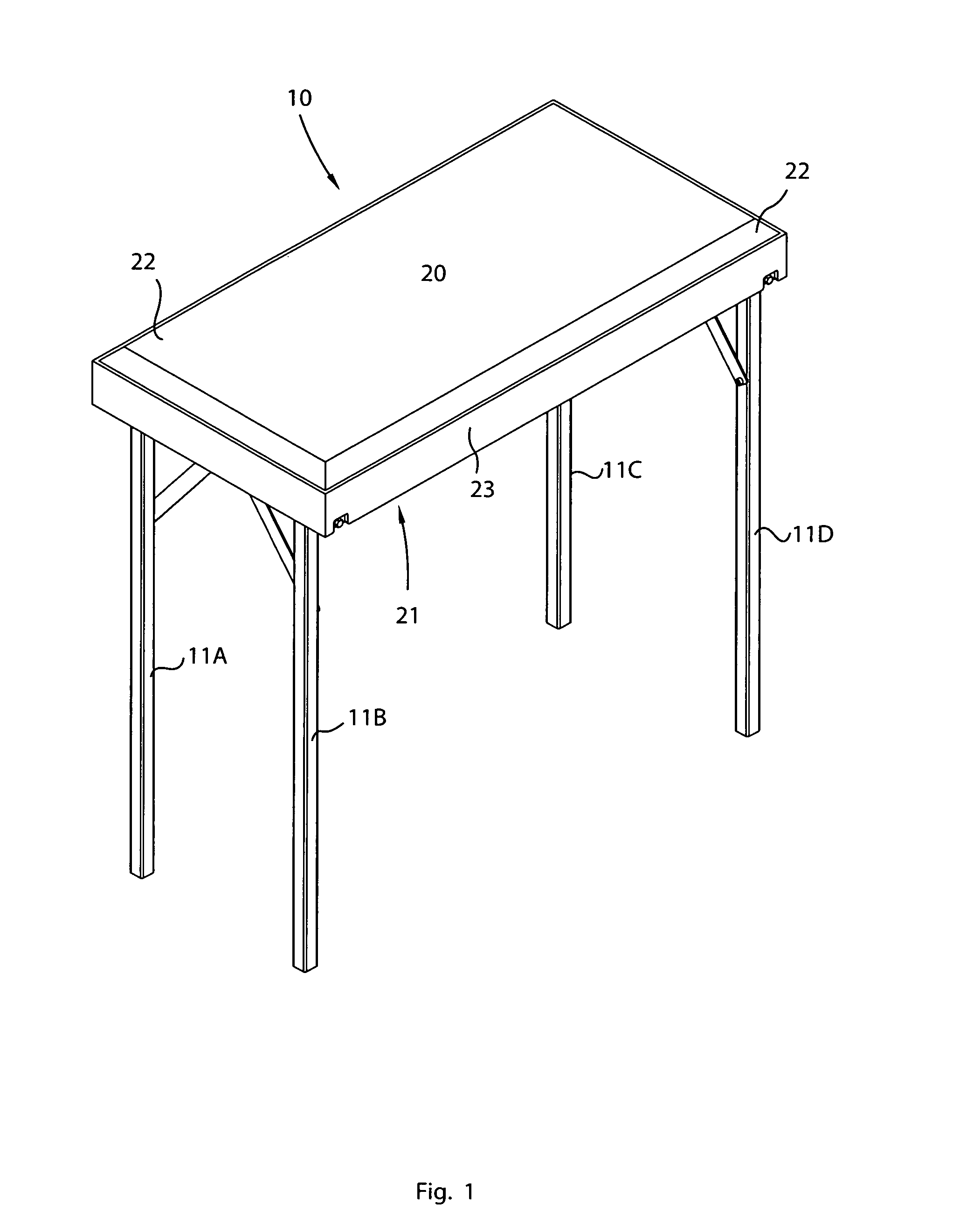
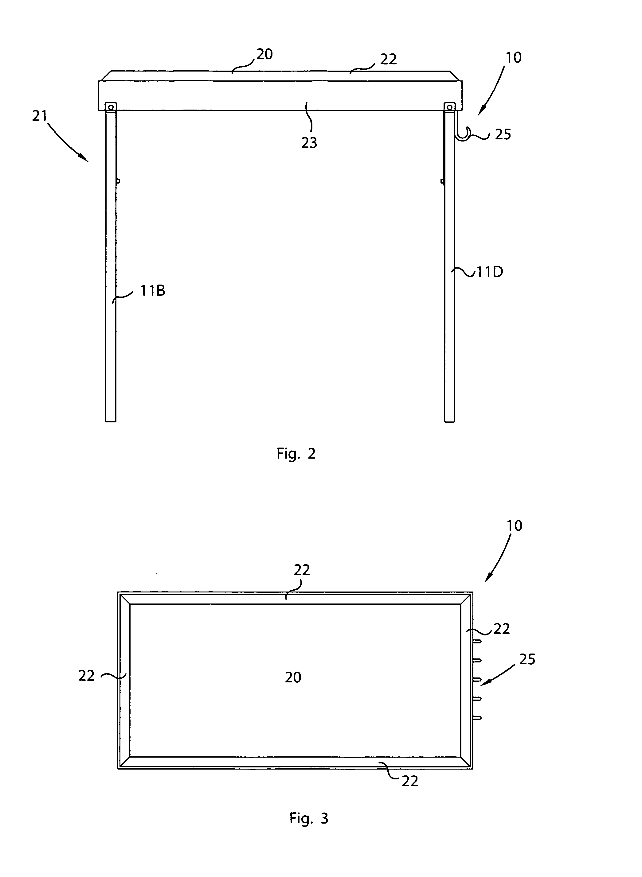
[0020]In one embodiment, the cutting surface may include a planar top-most surface registered along a horizontal plane. Such a cutting surface may also include a plurality of beveled edges obliquely offset from the horizontal plane. As an example, the beveled edges may be monolithically formed with an outer perimeter of the cutting surface. Notably, the beveled edges slope downwardly and away from the outer perimeter and terminate at in inner perimeter of the top-most region of the frame for effectively directing fluid and debris away from the top-most surface during cutting operations.
[0023]The frame biasing mechanism may further include a plurality of auxiliary support arms each preferably having axially opposed ends directly connected to a corresponding support leg and corresponding anchor rail, respectively. A plurality of secondary fastening members are directly anchored to the bottom wall and extend downwardly therefrom along a path registered orthogonal thereto. Each of such secondary fastening members may be removably coupled to a corresponding one of the auxiliary support arms when the frame is biased to the folded position such that the support legs are prohibited from prematurely pivoting to the unfolded position.

Problems solved by technology

Directly cutting objects upon a hard support which resists damage from a knife is known to unduly dull the knife when the object is severed.
Dulled cutlery requires additional force when severing work, and may lead to dangerous slipping and injury.
Yet maintaining the cutlery in a sharp state requires substantial sharpening time, and, when the cutlery is repeatedly dulled by the work support, the repeated sharpening also leads to undesired wear of the cutlery.
However, cutting without suitable work surfaces will likely result in unrestrained movement of the cutting blade.
This practice may lead to injury.
Furthermore, without a suitable support, foods may be contaminated by unsterile surfaces.
A similar issue arises with the use of a porous work support surface.
The porous surface will trap food juices therein, potentially contaminating the work surface and harboring dangerous pathogens.
As a consequence, it is impossible for a person to stop short of cutting all the way through the substrate and still obtain the desired result.
Where this work support is furniture or the like, the knife will cause harm and damage that may be irreparable.
In the outdoors or in areas less furnished, there may not be a ready work surface.
However, it will be apparent that the surface area of the cutting table and, relative to surface area, thinness of the table, does not lend the table to be readily transported, nor for storage in smaller spaces or places.
Not only does the traditional thin and flat cutting table suffer from an inconvenient size, the table must either be manufactured excessively thick to have adequate strength to avoid breakage, or may instead be excessively heavy.

Method used


Image

  • Portable cutting table and associated method
  • Portable cutting table and associated method
  • Portable cutting table and associated method

Examples


Embodiment Construction

[0040]The present invention will now be described more fully hereinafter with reference to the accompanying drawings, in which a preferred embodiment of the invention is shown. This invention may, however, be embodied in many different forms and should not be construed as limited to the embodiment set forth herein. Rather, this embodiment is provided so that this application will be thorough and complete, and will fully convey the true scope of the invention to those skilled in the art. Like numbers refer to like elements throughout the figures.

[0041]The present invention 10 is referred to generally in FIGS. 1-7 and is intended to provide a portable cutting table and associated carrying case 24. It should be understood that the cutting table may be used to accommodate many different types of cutting surfaces 20 such as wood, granite, stainless steal, or other suitable material well known by one skilled in the art, and should not be limited to any particular cutting surface 20. These...


PUM


Abstract

A portable cutting table may include a free-standing and collapsible frame adapted to be transported between remote locations. A cutting surface is preferably connected to a top-most region of the frame in such a manner that the cutting surface preferably remains centrally conjoined to the frame while the frame preferably is biased between folded and unfolded positions. A frame biasing mechanism articulates the frame between the folded and unfolded positions while the cutting surface remains statically engaged with the top-most surface. A plurality of knife-holding implements may be directly and fixedly mated to the frame biasing mechanism. Such knife-holding implements may be simultaneously articulated about a fulcrum axis registered orthogonal to a longitudinal axis of the cutting surface such that the knife-holding implements are automatically displaced between stored and exposed positions as the frame is biased between the folded and unfolded positions respectively.

Description

CROSS REFERENCE TO RELATED APPLICATIONS[0001]This application claims the benefit of U.S. Provisional Application No. 61 / 069,616, filed Mar. 17, 2008, the entire disclosures of which are incorporated herein by reference.STATEMENT REGARDING FEDERALLY SPONSORED RESEARCH OR DEVELOPMENT[0002]Not Applicable.REFERENCE TO A MICROFICHE APPENDIX[0003]Not Applicable.BACKGROUND OF THE INVENTION[0004]1. Technical Field[0005]This invention relates to cutting tables and, more particularly, to a portable cutting table including a support frame for holding a plurality of knife hooks and pivotal leg members for assisting in food preparation in a variety of locations.[0006]2. Prior Art[0007]Cutting tables have been in use for nearly as long as man has been civilized. The utility of a cutting table is derived from a need to cut various objects while simultaneously preserving the cutting edge of knives or blades. In the specific case of the culinary arts, the chef will also aspire to prepare foods in a ...

Claims


Application Information

Patent Timeline
Patent Type & Authority Patents(United States)
IPC IPC(8): B23Q3/00A47J17/00A47B37/00
CPCA47B3/08A47B13/08A47J47/005A47B33/00
Inventor IYEWARUN, ABAYOMI
Owner IYEWARUN ABAYOMI
Learn More