
Pneumatic turbine motor air chamber

a technology of pneumatic turbine and air chamber, which is applied in the direction of machines/engines, stators, liquid fuel engines, etc., can solve the problems of deformation or dislocation, uneven torque generated by pneumatic turbine rotors, etc., and achieve the effect of improving rotation smoothness

Active Publication Date: 2012-06-05
XPOLE PRECISION TOOLS
View PDF8 Cites 3 Cited by
  • Summary
  • Abstract
  • Description
  • Claims
  • Application Information

AI Technical Summary

Benefits of technology

[0005]The primary object of the present invention is to solve the aforesaid disadvantage and provides a torque to generate steady rotation of a pneumatic turbine motor and improve rotation smoothness thereof.

Problems solved by technology

However, as the barrier is located separately in the turbine, when in use it is deformed or dislocated due to pressing of the O-ring caused by the compressed air, or even broken.
As a result, the torque generated by the pneumatic turbine rotor is uneven.

Method used


Image

  • Pneumatic turbine motor air chamber
  • Pneumatic turbine motor air chamber
  • Pneumatic turbine motor air chamber

Examples


Embodiment Construction

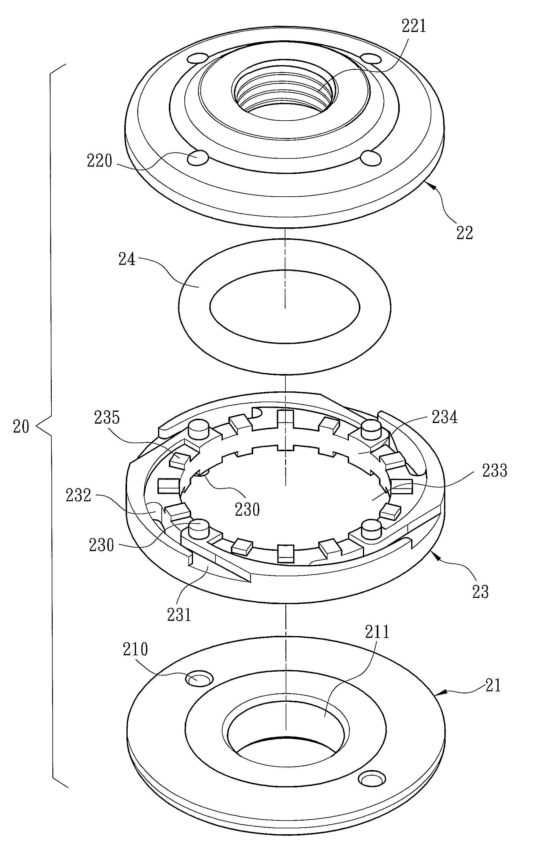
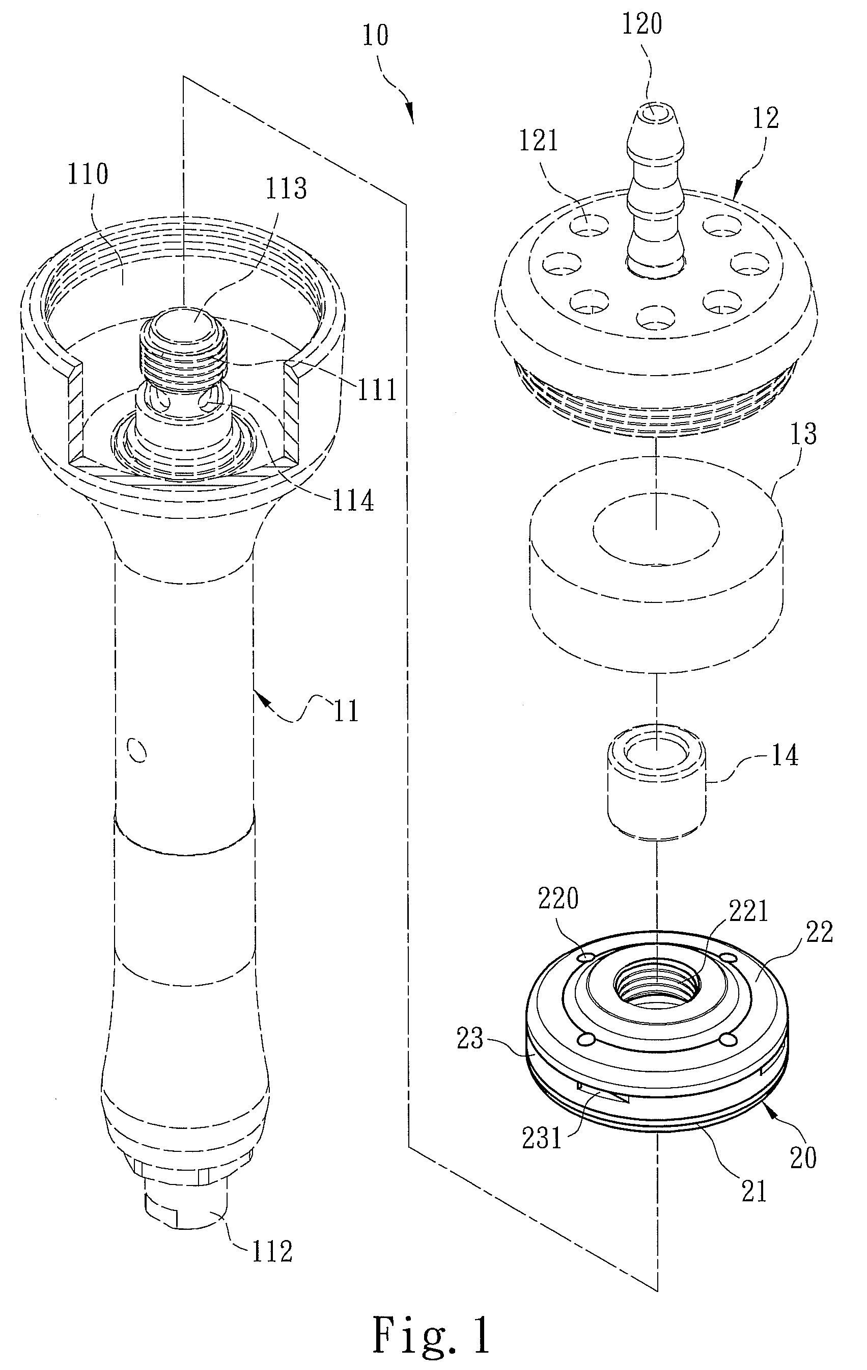
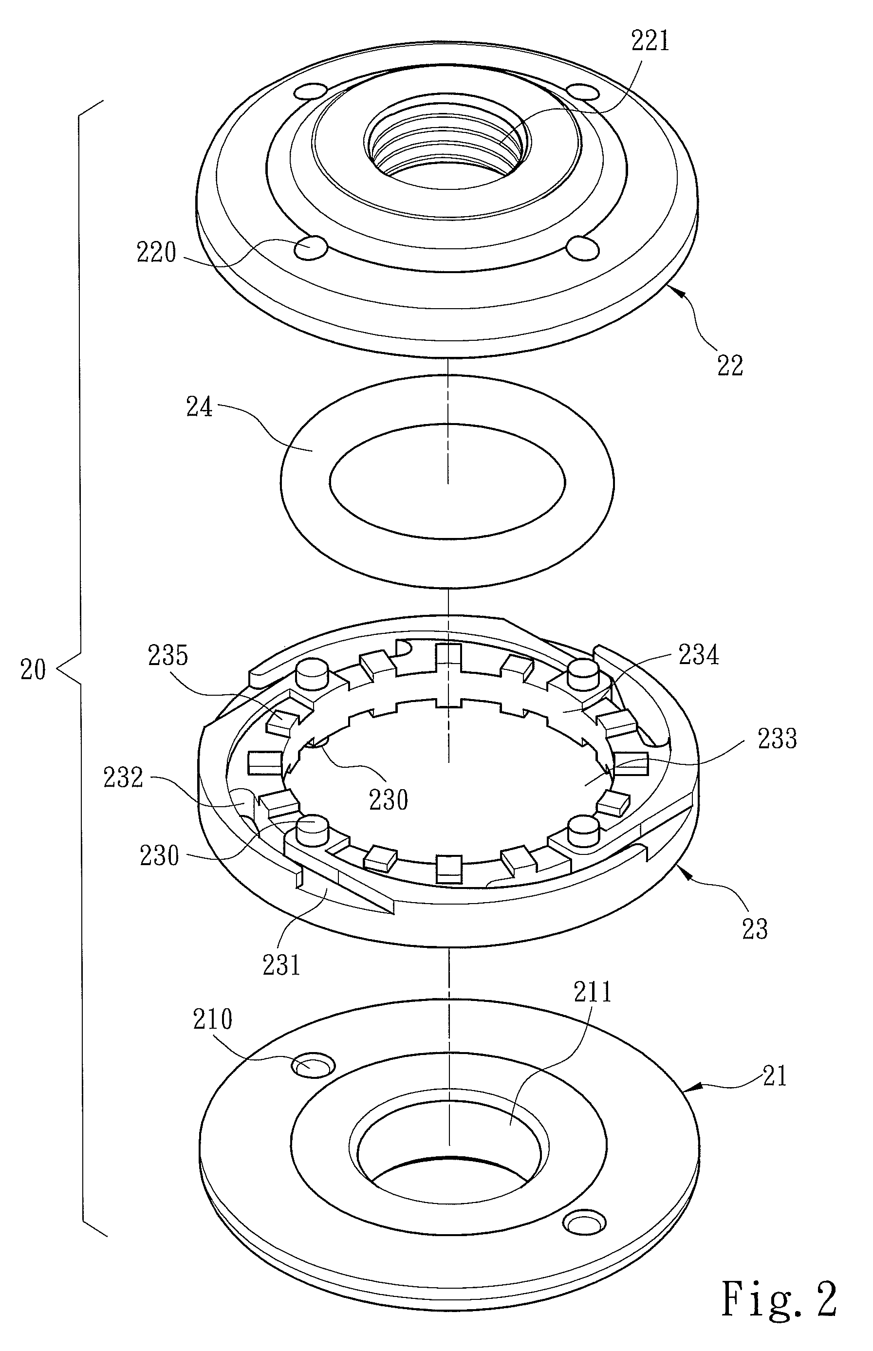
[0013]Please refer to FIG. 1, the pneumatic turbine motor air chamber according to the invention mainly aims to be used on a pneumatic turbine 20 of a pneumatic tool 10. The pneumatic tool 10 has a tool body driven by compressed air to do work on an object. The tool body includes a hand grip 11 and a base 12. The base 12 has an air inlet 120 and a plurality of air outlets 121, and a bottom side coupling with a muffler 13 and an intake sealing sleeve 14. There is a housing compartment 110 formed between the hand grip 11 and the base 12 to hold the pneumatic turbine 20, muffler 13 and intake sealing sleeve 14. The handgrip 11 also holds a spindle 111 extended into the housing compartment 110. The spindle 111 is partially hollow and has an air channeling vent 113 connecting to the intake sealing sleeve 14 and a plurality of openings 114 to form an air intake passage. The pneumatic turbine 20 has an intake coupling hole 221 coupling with the spindle 111 to be rotated therewith at the sa...


PUM


Abstract

A pneumatic turbine motor air chamber drives a pneumatic turbine to rotate through compressed air. The pneumatic turbine has a ring extended from inside thereof that has a plurality of barriers and forms a housing space to hold a speed regulator. The pneumatic turbine also has an air intake coupling hole leading to the housing space and at least one air discharge vent communicating with an air passage to discharge the compressed air. The ring is integrally formed with the pneumatic turbine to enhance operation steadiness of the pneumatic turbine.

Description

FIELD OF THE INVENTION[0001]The present invention relates to a structure of a pneumatic turbine motor air chamber and particularly to a motor to generate rotation through a pneumatic turbine driven by compressed air to be used on a pneumatic tool.BACKGROUND OF THE INVENTION[0002]A conventional pneumatic tool has a pneumatic turbine motor driven by compressed air to generate rotation. The pneumatic turbine rotates to generate a centrifugal force which incorporates with a flexible O-ring to control the size of an air inlet and an outlet to stabilize rotation speed of the pneumatic turbine motor.[0003]For instance U.S. Pat. No. 7,077,732 discloses a dual chamber turbine rotor which has a turbine including a spacer and a front cap and a rear cap at two ends to form a first chamber and a second chamber. The front cap and rear cap and two sides of the spacer have respectively a corresponding trough to hold a barrier. The first and second chambers hold respectively an O-ring and have an ai...

Claims


Application Information

Patent Timeline
Patent Type & Authority Patents(United States)
IPC IPC(8): F04D29/44
CPCF01D1/02F01D15/067
Inventor CHENG, WEI-HUA
Owner XPOLE PRECISION TOOLS
Learn More