Method and system for detection of contrast injection in fluoroscopic image sequences

a fluoroscopic image and contrast injection technology, applied in the field of contrast injection detection in fluoroscopic image sequences, can solve the problem that blood filled structures cannot be differentiated from surrounding tissue using conventional radiology

Inactive Publication Date: 2012-06-05
SIEMENS HEALTHCARE GMBH
View PDF13 Cites 3 Cited by
  • Summary
  • Abstract
  • Description
  • Claims
  • Application Information

AI Technical Summary

Problems solved by technology

Since blood has the same radiodensity as the surrounding tissues, these blood filled structures cannot be differentiated from the surrounding tissue using conventional radiology.

Method used


Image

  • Method and system for detection of contrast injection in fluoroscopic image sequences
  • Method and system for detection of contrast injection in fluoroscopic image sequences
  • Method and system for detection of contrast injection in fluoroscopic image sequences

Examples


Embodiment Construction

[0019]The present invention relates to detection of a contrast injection time and location in a fluoroscopic image sequence. Embodiments of the present invention are described herein to give a visual understanding of the contrast injection detection method. A digital image is often composed of digital representations of one or more objects (or shapes). The digital representation of an object is often described herein in terms of identifying and manipulating the objects. Such manipulations are virtual manipulations accomplished in the memory or other circuitry / hardware of a computer system. Accordingly, is to be understood that embodiments of the present invention may be performed within a computer system using data stored within the computer system.

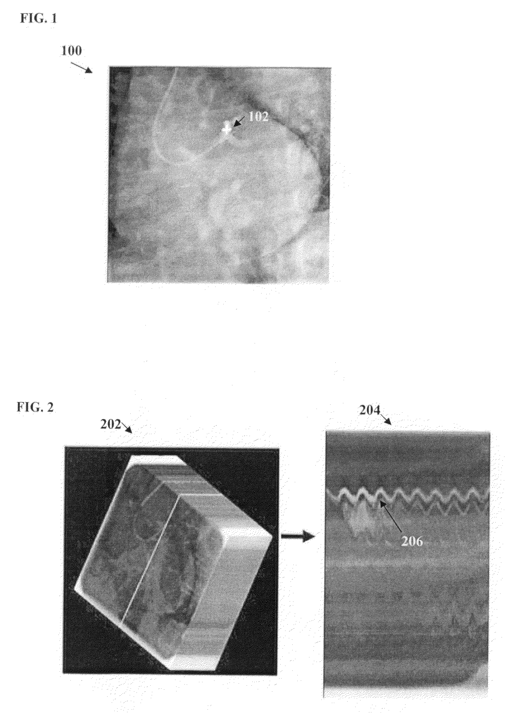
[0020]A sequence of fluoroscopic images contains multiple 2D X-ray images obtained in real time. FIG. 1 illustrates an exemplary fluoroscopic image showing the start of a contrast injection. As illustrated in FIG. 1, image 100 is a fluoro...


PUM


Abstract

A method and system for detecting a spatial and temporal location of a contrast injection in a fluoroscopic image sequence is disclosed. Training volumes generated by stacking a sequence of 2D fluoroscopic images in time order are annotated with ground truth contrast injection points. A heart rate is globally estimated for each training volume, and local frequency and phase is estimated in a neighborhood of the ground truth contrast injection point for each training volume. Frequency and phase invariant features are extracted from each training volume based on the heart rate, local frequency and phase, and a detector is trained based on the training volumes and the features extracted for each training volume. The detector can be used to detect the spatial and temporal location of a contrast injection in a fluoroscopic image sequence.

Description

[0001]This application claims the benefit of U.S. Provisional Application No. 60 / 974,100, filed Sep. 21, 2007, the disclosure of which is herein incorporated by reference.BACKGROUND OF THE INVENTION[0002]The present invention relates to detection of contrast injection in fluoroscopic image sequences, and more particularly to detection of where and when a contrast agent is injected in a fluoroscopic image sequence.[0003]Coronary angiography is a procedure that is recommended preoperatively for patients who are suffering from or at risk for coronary artery disease. Angiography is a medical imaging technique in which X-ray images are used to visualize internal blood filled structures, such as arteries, veins, and the heart chambers. Since blood has the same radiodensity as the surrounding tissues, these blood filled structures cannot be differentiated from the surrounding tissue using conventional radiology. In angiography, a catheter is inserted into a blood vessel, typically in the g...

Claims


Application Information

Patent Timeline
Patent Type & Authority Patents(United States)
IPC IPC(8): G06K9/00G06V20/50
CPCG06K9/00G06T7/0012G06K2209/05G06V2201/03G06V20/50G06F18/00
Inventor SAPP, BENJAMIN J.ZHANG, WEIGEORGESCU, BOGDANPRUMMER, SIMONECOMANICIU, DORIN
Owner SIEMENS HEALTHCARE GMBH
Why Eureka
Try Eureka