Device and method for synchronizing the states of a plurality of sequential processing units

a technology of synchronizing state and sequential processing, applied in the direction of transmission, electric digital data processing, instruments, etc., can solve the problems of receiving errors, affecting the quality of the signal, and the output of the ascending processor does not match the original data, so as to achieve the effect of ensuring the quality of the signal

Active Publication Date: 2012-06-05
ROHDE & SCHWARZ GMBH & CO KG
View PDF12 Cites 0 Cited by
  • Summary
  • Abstract
  • Description
  • Claims
  • Application Information

AI Technical Summary

Benefits of technology

[0040]For example, a synchrony between multiple circuits may be achieved by inserting a variable delay element in the clock path leading to each circuit. Typically, the delay tuning range extends over only a fraction of the clock period. In this case, this technique only enables fine-tuning the relative phases at which the circuits operate. Theoretically however, the delay tuning range could extend over multiple clock periods. By increasing the delay setting slowly and continuously by one clock period, it would be possible to shift the state of a circuit by one unit with respect to other circuits running on the same clock signal. However, this technique can provide only limited shifting of circuit states because variable delay elements have a finite delay tuning range. Thus, the clock processing means may delay the common clock signal.
[0070]According to the invention, the state of the circuit influenced by the phase dial can be shifted by any number of clock cycles. By contrast, the variable-delay technique can produce only limited shifts—typically less than a clock cycle. Furthermore, a phase dial can be implemented on the basis of a single fixed-delay element with a delay of one quarter of a clock period while supporting an unlimited tuning range. The variable-delay technique requires a variable delay element with a tuning range of N clock periods to produce a shifting range limited to N clock cycles. Thus, even in applications where a limited tuning range would be acceptable, the phase dial approach will generally be less costly to implement.

Problems solved by technology

If the states of the transmitter PRBS generator and the receiver PRBS generator are not properly synchronized then the descrambler output does not match the original data and reception errors occur.
If the deserializer begins to operate at a random point in the bit stream then the output words may be shifted with respect to the original words which results in reception errors.
However, if the distance between circuits is non-negligible compared to the clock wavelength then timing errors exceeding a clock period may occur due to mismatches between the lengths of electrical paths, between the driver characteristics and between the termination impedances.
As a result, when this circuit resumes normal operation, its state has been delayed with respect to the states of the other circuits.
At very high clock frequencies, it may not be practical to distribute a common reset signal to multiple circuits to be synchronized.
If the distance between circuits is greater than the wavelength of the clock signal, it may become challenging to achieve good delay matching between the clock signal path and the reset signal path, whereby proper timing relationships between the clock and the reset signals become difficult to guarantee.
However, such a self-synchronizing scheme is suited only for this specific application.
It also has the drawback that the scrambler can remain locked in an unwanted state for some incoming data sequences.
However, the number of logic gates required to implement a B-bit barrel shifter grows with the square of B which is associated with an increasing in hardware complexity and power consumption.
The timing patterns recorded in subsequent measurements can be corrected on this basis which is, however, associated with an increased complexity.

Method used


Image

  • Device and method for synchronizing the states of a plurality of sequential processing units
  • Device and method for synchronizing the states of a plurality of sequential processing units
  • Device and method for synchronizing the states of a plurality of sequential processing units

Examples


Embodiment Construction

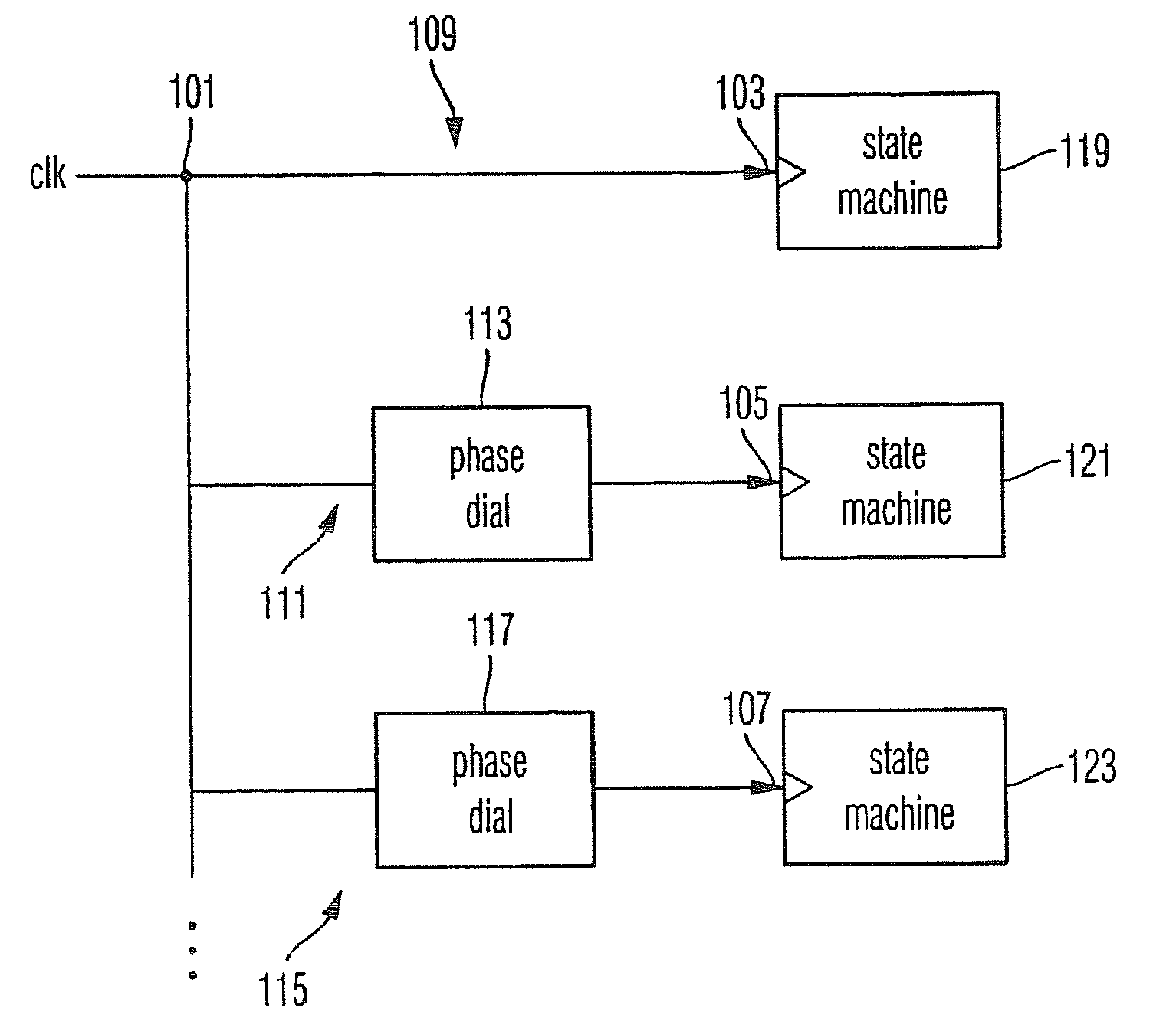
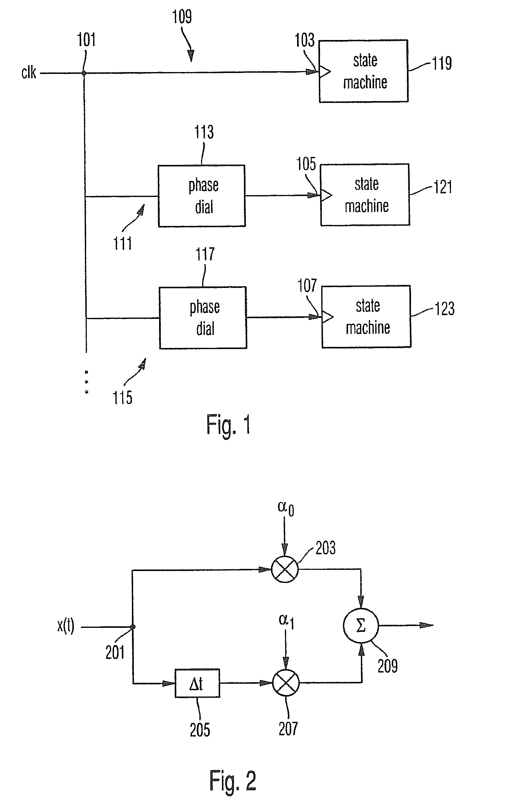
[0078]The inventive approach may be used for synchronizing the states of multiple circuits running on a common clock signal, especially in applications where the distribution of a common reset signal to all circuits is not practical. The block diagram depicted in FIG. 1 depicts the case of three circuits as an example, but the approach generalizes to any number of circuits. After starting the circuits from random initial states, offsets between states are measured. One of the circuits can be chosen as a reference and the states of all other circuits can be shifted ahead or back with respect to the reference circuit by rotating the related phase dial over the number of full turns required to bring the error down to zero. Thus, it is possible to avoid providing a phase dial rotating a phase of a clock signal for the reference circuit. Thus, a calibration of the relative phases at which the circuits update their states can be achieved without additional hardware. Instead of rotating a ...


PUM


Abstract

A device for providing a plurality of clock signals from a common clock signal. The device includes an input for receiving the common clock signal, a first clock signal path for providing a first output clock signal on the basis of the common clock signal and a second clock signal path for providing a second output clock signal. The second clock signal path includes a clock processing device for changing a phase of the common clock signal to provide the second clock signal.

Description

CROSS-REFERENCE TO RELATED APPLICATION[0001]The present application claims priority to PCT Application No. PCT / EP2007 / 008207, filed on Sep. 20, 2007, and European Application No. 06 021 435.0, Filed on Oct. 12, 2006, the entire contents of which are herein incorporated by reference.BACKGROUND OF THE INVENTION[0002]1. Field of the Invention[0003]The present invention relates to setting the states of multiple sequential processing units into mutually compatible states without resorting to a common reset signal.[0004]2. Discussion of the Background[0005]In order to synchronously operate a plurality of sequential electronic circuits arranged e.g. within an electronic system, all involved circuits must be set into mutually compatible states at some point in time. Provided that all involved circuits update their state under control of a clock signal derived from a common reference clock, their states will remain synchronous ever after.[0006]The need to synchronize the states of multiple c...

Claims


Application Information

Patent Timeline
Patent Type & Authority Patents(United States)
IPC IPC(8): G06F1/04G06F1/12
CPCG06F1/06
Inventor LANDOLT, OLIVER
Owner ROHDE & SCHWARZ GMBH & CO KG
Why Eureka
Try Eureka